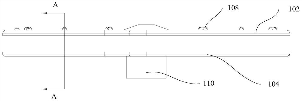
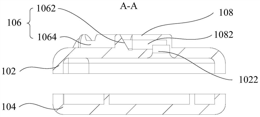
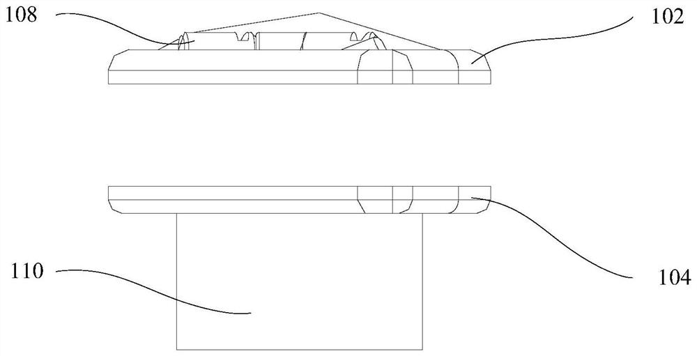
Spray Arms and Cleaning Units

A technology of cleaning device and spray arm, applied in the directions of spray device, spray device, liquid spray device, etc., can solve the problems of increased cleaning time, limited cleaning area of ​​spray arm, waste of cleaning liquid, etc.

Active Publication Date: 2021-05-04
MIDEA GRP CO LTD
View PDF5 Cites 0 Cited by
  • Summary
  • Abstract
  • Description
  • Claims
  • Application Information

AI Technical Summary

Problems solved by technology

[0002] At present, in the related technology, the nozzles on the spray arm are all in the shape of round holes, and the water flow ejected from the nozzles is a cylindrical jet. Since the coverage of the cylindrical jet is small, the cleaning area of ​​the spray arm is also limited. Uneven cleaning and poor cleaning effect; at the same time, due to the small cleaning area of ​​this spray arm, if you want to clean the tableware, you must increase the cleaning time, which causes a waste of cleaning liquid. Therefore, how to design a cleaning It is very necessary to have a spray arm with a large area and save cleaning fluid

Method used


Image

  • Spray Arms and Cleaning Units
  • Spray Arms and Cleaning Units
  • Spray Arms and Cleaning Units

Examples


Embodiment Construction

[0038]In order to understand the above-mentioned purpose, features and advantages of the present invention more clearly, the present invention will be further described in detail below in conjunction with the accompanying drawings and specific embodiments. It should be noted that, in the case of no conflict, the embodiments of the present application and the features in the embodiments can be combined with each other.

[0039] In the following description, many specific details are set forth in order to fully understand the present invention. However, the present invention can also be implemented in other ways different from those described here. Therefore, the protection scope of the present invention is not limited by the specific details disclosed below. EXAMPLE LIMITATIONS.

[0040] Refer below Figure 1 to Figure 6 The spray arm and cleaning device according to some embodiments of the present invention are described.

[0041] In the embodiment of the first aspect of the...


PUM


Abstract

The invention provides a spray arm and a cleaning device, which are used for cleaning the device. The spray arm includes: a first body, a second body, a guide part and a nozzle; the second body and the first body form a hollow cavity; the guide The flow part is located on the outer wall of the first body, and one side of the flow guide part is a flow guide surface; the nozzle is arranged on the outer wall of the first body, and a flow channel is arranged in the nozzle, and the flow channel communicates with the hollow cavity; the flow channel is along the The outer wall of the first body is extended so that the cleaning fluid flows out along the outer wall of the first body and hits the flow guide surface. Since the cleaning liquid is diverted by the diversion surface, the jet area of ​​the cleaning liquid is increased, so the cleaning range of the spray arm is also expanded, which avoids the occurrence of cleaning dead angles caused by the incomplete coverage of the cleaning range of the spray arm; at the same time , due to the expansion of the cleaning range of the spray arm, the time used for cleaning the spray arm is reduced, thereby achieving the technical effect of saving cleaning fluid and reducing the use cost of the product.

Description

technical field [0001] The invention relates to a cleaning device, in particular to a spray arm and a cleaning device. Background technique [0002] At present, in the related technology, the nozzles on the spray arm are all in the shape of round holes, and the water flow ejected from the nozzles is a cylindrical jet. Since the coverage of the cylindrical jet is small, the cleaning area of ​​the spray arm is also limited. Uneven cleaning and poor cleaning effect; at the same time, due to the small cleaning area of ​​this spray arm, if you want to clean the tableware, you must increase the cleaning time, which causes a waste of cleaning liquid. Therefore, how to design a cleaning It is very necessary to have a spray arm with a large area and save cleaning fluid. Contents of the invention [0003] The present invention aims to solve at least one of the technical problems existing in the prior art or related art. [0004] To this end, a first aspect of the invention propose...

Claims


Application Information

Patent Timeline
Patent Type & Authority Patents(China)
IPC IPC(8): B05B1/26B05B9/04
CPCB05B1/262B05B9/0403
Inventor 蓝渊张辉
Owner MIDEA GRP CO LTD
Why Eureka
Try Eureka