Supercharge Your Innovation With Domain-Expert AI Agents!

Comparator circuit and infrared signal receiver

A technology of comparing circuits and circuits, applied in non-electrical signal transmission systems, exclusive-or circuits, signal transmission systems, etc., can solve the problems of longer ON cycle, insufficient guarantee of hysteresis voltage width, etc.

Inactive Publication Date: 2006-03-22
SHARP KK
View PDF1 Cites 0 Cited by
  • Summary
  • Abstract
  • Description
  • Claims
  • Application Information

AI Technical Summary

Problems solved by technology

However, this is not enough for the working voltage of 2.4v or 1.8v. In recent years, 2.4v or 1.8v has been required as the lowest working voltage for the advocated low voltage
[0014] Moreover, when the limit voltage Vlimit is set high enough or the limiter circuit 3 is not set, the ON period of the output becomes longer, and the pulse width becomes wider than required.
Since the use of low voltage is advocated, the hysteresis voltage width Vhis cannot be guaranteed sufficiently, and malfunctions such as oscillations may occur

Method used


Image

  • Comparator circuit and infrared signal receiver
  • Comparator circuit and infrared signal receiver
  • Comparator circuit and infrared signal receiver

Examples


Embodiment Construction

[0053] Referring now to the accompanying drawings, preferred embodiments of the present invention will be described below.

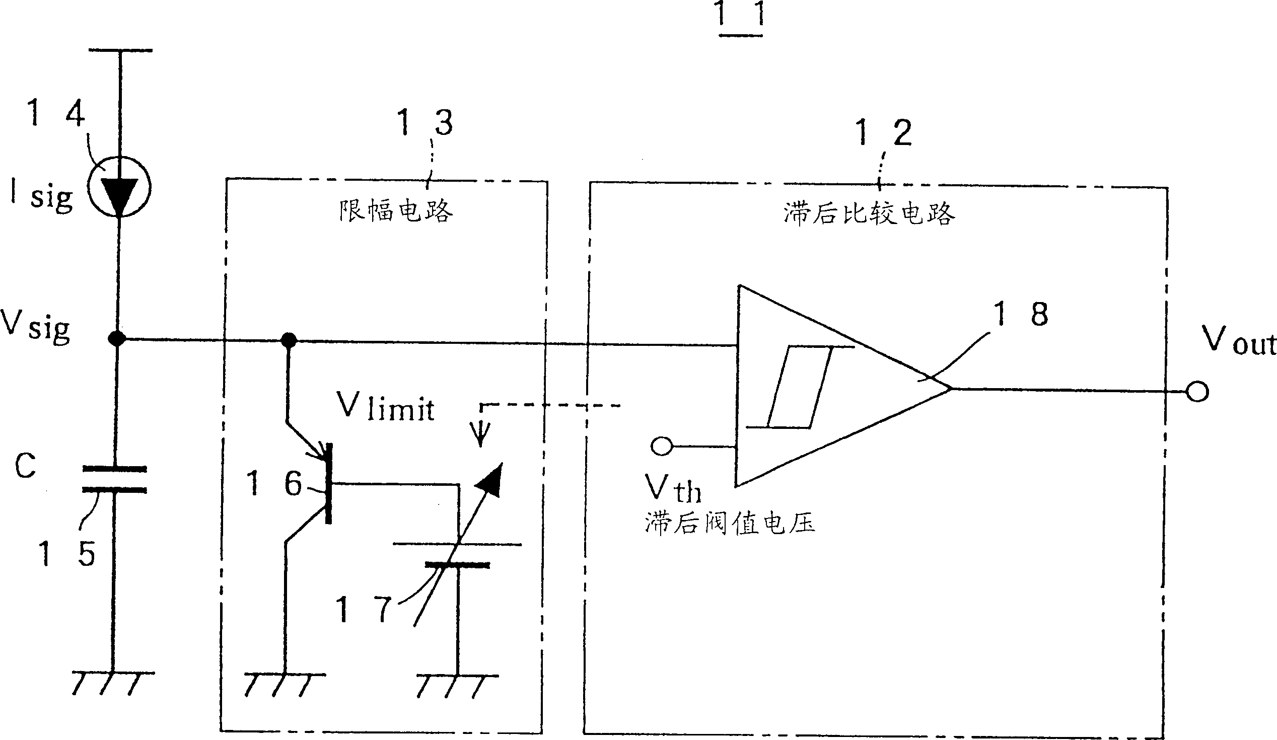
[0054] figure 1 is a block diagram of a schematic circuit configuration of the comparison circuit 11 according to an embodiment of the present invention. The comparator circuit 11 of this embodiment is intended to limit the input voltage input to the hysteresis comparator circuit 12 by the limiter circuit 13 to prevent saturation of the input portion. The input voltage Vsig input to the limiter circuit 13 is the terminal voltage at which an integrating capacitor 15 with a capacity C is charged with a signal current Isig from an infrared receiving device, a high-sensitivity sensor 14, and the like. The limiter circuit 13 for limiting the input voltage Vsig includes a PNP transistor 16 and a bias circuit 17 . The hysteresis comparison circuit 12 includes a hysteresis comparator 18 having a hysteresis characteristic. The bias circuit 17 of the present em...


PUM


Abstract

The present invention has an object to control easily the pulse width of an output by operating a limiting circuit appropriately-even if the power voltage is low. A limiting circuit 13 is provided on the input side of a hysteresis comparator circuit 12 to prevent saturation. A limit voltage Vlimit is set by a bias circuit 17 so as to change in accordance with the operation of the hysteresis comparator circuit 12. When an input voltage Vsig exceeds a hysteresis threshold voltage Vth, the limit voltage Vlimit is dropped in response to a drop of the hysteresis threshold voltage Vth. Thus, the width of the pulse width can be controlled while maintaining the condition that the limit voltage Vlimit is higher than the hysteresis threshold voltage Vth.

Description

technical field [0001] The present invention relates to a comparator circuit for discriminating output voltage and outputting logic output indicating discriminating result, and an infrared signal receiving device realized by using the comparator circuit. Background technique [0002] Generally, the comparison circuit 1 shown in FIG. 8 is used, for example, to discriminate an integrated output voltage using a receiver of an infrared remote control device or to discriminate an output of a high-sensitivity sensor or the like. The comparison circuit 1 uses a hysteresis comparison circuit 2 having a hysteresis characteristic at a discrimination potential. The hysteresis comparison circuit 2 compares the input voltage with the discrimination potential, and when the input voltage is higher than the discrimination potential, the output Vout is turned on. At the same time, the discrimination potential will drop to prevent the output Vout from being cut off even if the input voltage ...

Claims


Application Information

Patent Timeline
Patent Type & Authority Patents(China)
IPC IPC(8): H03K19/20H03K19/21G08C13/00G08C23/04H03K3/0233H03K3/2897H03K5/08H03K5/24
CPCH03K5/2418H03K3/02337H03K3/2897
Inventor 井上高广横川成一西野毅
Owner SHARP KK
Features
  • R&D
  • Intellectual Property
  • Life Sciences
  • Materials
  • Tech Scout
  • Unparalleled Data Quality
  • Higher Quality Content
  • 60% Fewer Hallucinations
Learn More