Color cathode ray tube

A cathode ray tube, color technology, applied in the direction of cathode ray tube/electron beam tube, cathode ray/electron beam tube shell/container, screen tube, etc., can solve problems such as image quality deterioration

Inactive Publication Date: 2006-04-12
KK TOSHIBA
View PDF2 Cites 0 Cited by
  • Summary
  • Abstract
  • Description
  • Claims
  • Application Information

AI Technical Summary

Problems solved by technology

In this case, the quality of the image deteriorates

Method used


Image

  • Color cathode ray tube
  • Color cathode ray tube
  • Color cathode ray tube

Examples


Embodiment Construction

[0083] Hereinafter, a color cathode ray tube related to an embodiment of the present invention will be described in detail with reference to the accompanying drawings.

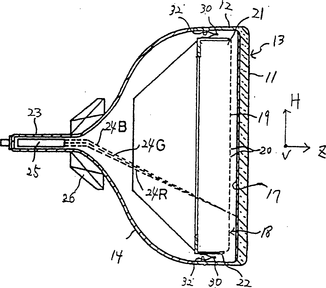
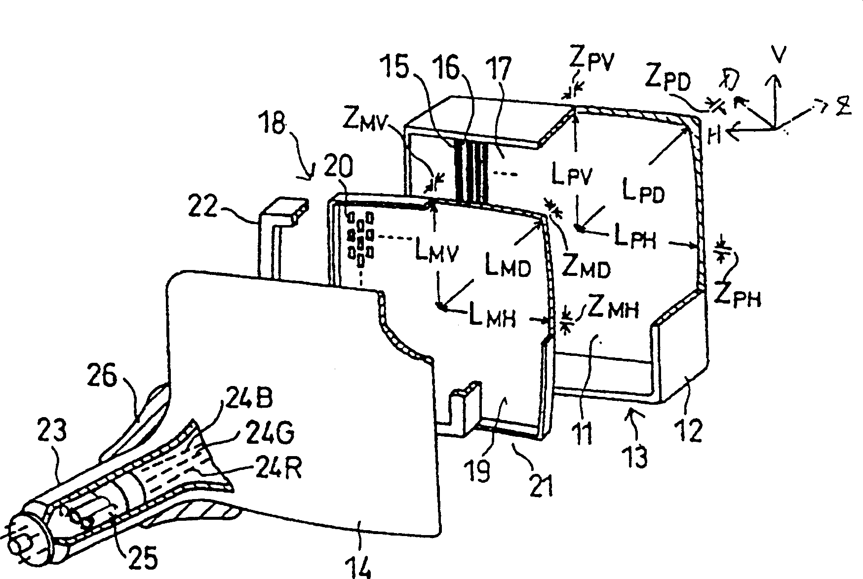
[0084] Such as figure 1 and figure 2 As shown, the color cathode ray tubes all have a generally rectangular face plate 13 and an envelope with a funnel-shaped cone. The panel 14 includes a curved effective portion 11 and a skirt portion 12 provided around the effective portion. A funnel-shaped cone 14 engages the skirt portion. A phosphor screen 17 composed of a black non-luminous layer and three-color phosphor layers 16 formed as if embedded in the gap between the black non-luminous layers is attached to the inner side of the effective part 11 of the panel 13 . In addition, a substantially rectangular shadow mask 18 is arranged inside the panel 13 to face the fluorescent screen 17 .

[0085] The shadow mask 18 is composed of a substantially rectangular mask main body 21 formed by press molding and a subs...


PUM


Abstract

A color cathode ray tube comprises a face panel having a phosphor screen formed on the inner surface thereof and a shadow mask. A mask body of the shadow mask has an effective surface opposed to the phosphor screen and formed having a plurality of electron beam passage apertures. The face panel and mask body are formed so as to establish relations: ZPD>ZPV>ZPH, ZMD>ZMH>ZMV, ZPDZMV, where ZPD, ZPH, and ZPV are sags at a diagonal-axis end, horizontal-axis end, and vertical-axis end, respectively, with respect to the center of the inner surface of the face panel, and ZMD, ZMH, and ZMV are sags at the individual axis ends with respect to the center of the effective surface of the mask body.

Description

[0001] Cross References to Related Applications [0002] This application is based on Japanese Patent Application No. 2001-054701 filed on February 28, 2001, the priority of which is claimed and the entire contents of which are hereby incorporated by reference. technical field [0003] The present invention relates to a color cathode ray tube with a shadow mask. Background technique [0004] A typical color cathode ray tube has a generally rectangular faceplate and a bulb with a funnel-shaped cone. The panel includes a curved effective portion and a skirt portion provided around the effective portion. The funnel-shaped cone engages the skirt portion. A phosphor screen consisting of a black non-luminous layer and three-color phosphor layers embedded in the gap between the black non-luminous layers is attached to the inner side of the effective part of the panel. In addition, a substantially rectangular shadow mask is disposed inside the panel facing the fluorescent panel. ...

Claims


Application Information

Patent Timeline
Patent Type & Authority Patents(China)
IPC IPC(8): H01J29/86H01J29/07H01J31/20
CPCH01J29/861H01J29/07H01J2229/0788H01J2229/0794H01J2229/862
Inventor 清水纪雄井上雅及
Owner KK TOSHIBA
Why Eureka
Try Eureka