Peristaltic pump

a peristaltic pump and pump body technology, applied in the direction of machines/engines, positive displacement liquid engines, tableware washing/rinsing machine details, etc., can solve the problems of loss of pump functional capability, peristaltic pump known design still comparatively expensive, and cover breakag

Inactive Publication Date: 2005-11-17
ECOLAB USA INC
View PDF9 Cites 31 Cited by
  • Summary
  • Abstract
  • Description
  • Claims
  • Application Information

AI Technical Summary

Benefits of technology

[0011] It can be advantageous if an end wall with a detent tongue as well as with two substantially U-shaped recesses for passage of the squeeze hose is provided at the housing base, wherein in a further embodiment it can be provided that the setting lever is constructed as a yoke with counter-detent for detenting at the detent tongue in the housing closed setting. In that case it is possible to provide with the same detent element a carrier not only for the squeeze hose bend, but also for the setting lever or setting yoke.

Problems solved by technology

It has proved that the known designs of peristaltic pumps are still comparatively costly, wherein in the case of the first solution the exchange, which is necessary from time to time, of the squeeze hose bend is possible only by screwing on the cover, whereas in the case of the solution provided with the pivot cover a disadvantage arises, in particular, in the susceptibility of the cover to breakage and thus loss of the functional capability of the pump.

Method used


Image

  • Peristaltic pump
  • Peristaltic pump
  • Peristaltic pump

Examples


Embodiment Construction

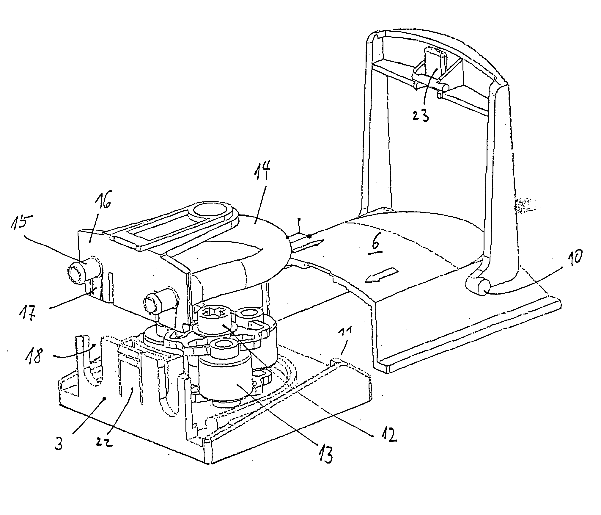
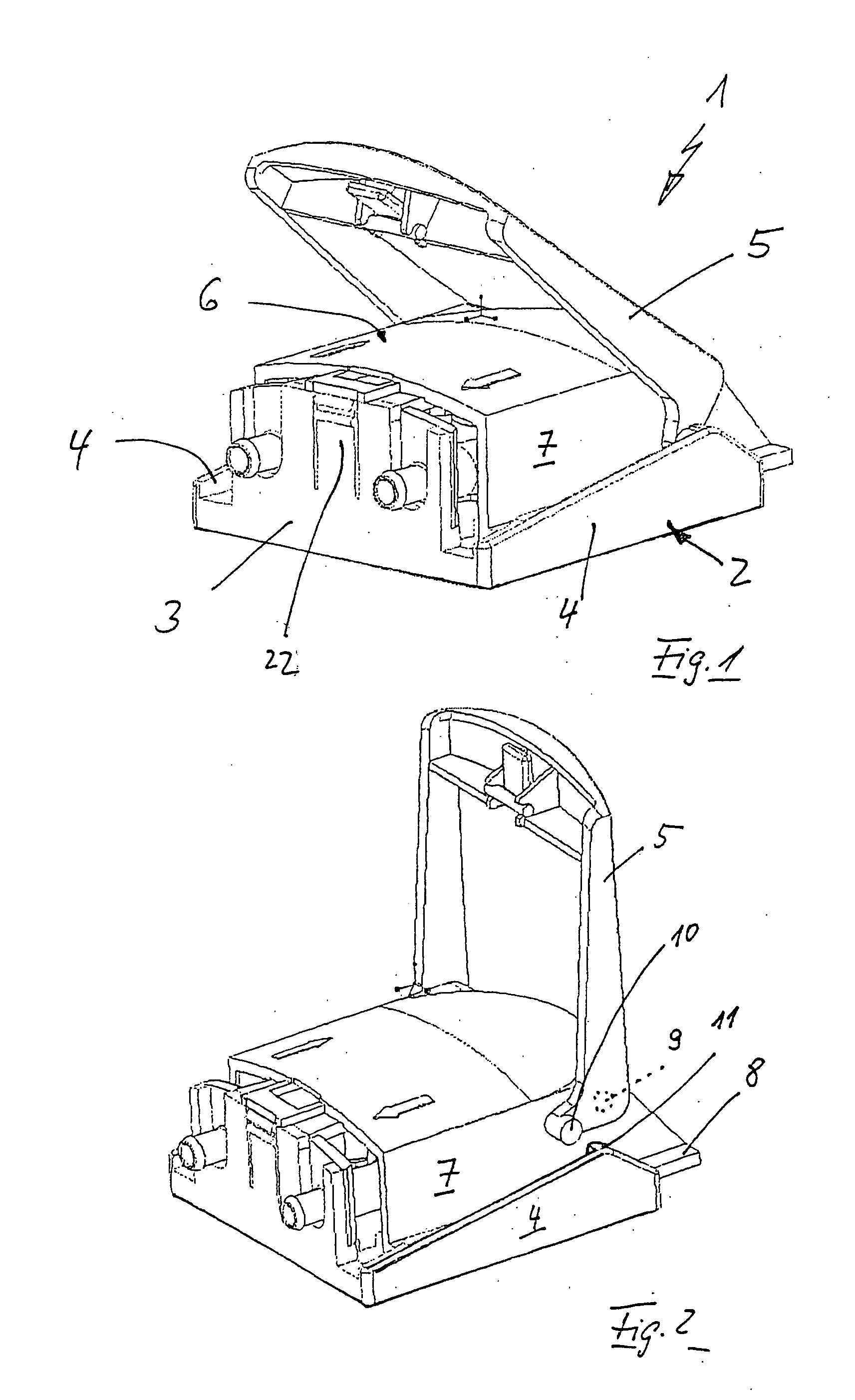
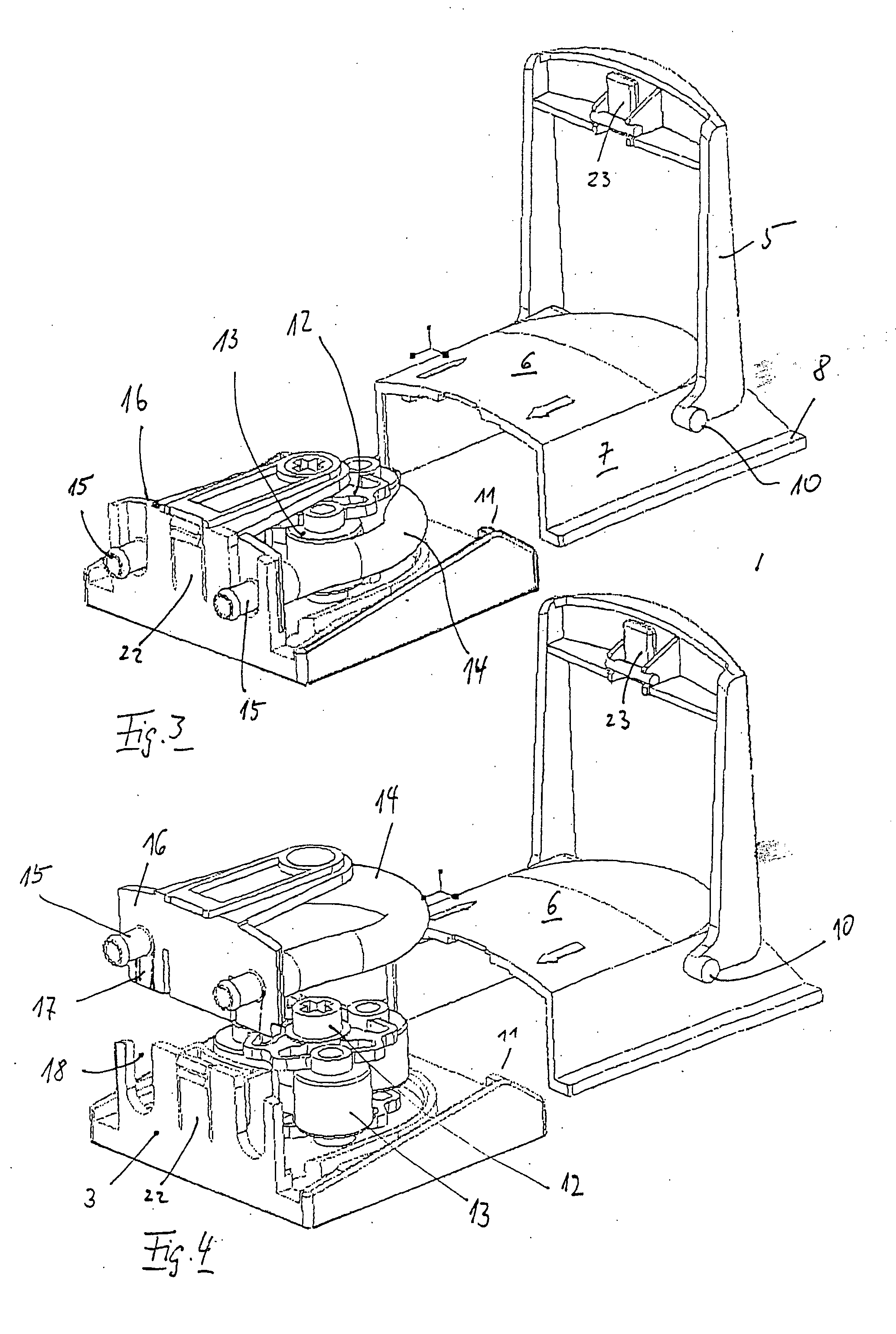
[0017] The pump head denoted generally by 1 comprises a base element 2 whith an integrally formed end wall 3 and two side walls 4 which are in turn integrally formed therewith, as well as a housing cover 6 which is displaceable by way of a pivot lever 5, and which in turn has integrally formed side wall surfaces 7 parallel to the side wall surfaces 4 of the base part. The side wall surfaces 7 of the housing cover have, at the lower outer edge thereof, integrally formed slide rails 8 which are displaceable guided in corresponding counter rails or grooves in the region of transition from the base of the side wall surfaces 4.

[0018] As evident particularly from FIG. 2, the pivot yoke 5 is pivotably mounted at the cover 6 by way of inwardly pointing hinge pins 9, wherein outwardly pointing pins 10 can bear against pivot projections 11 which are integrally formed at the side walls 4 of the base part to pint inwardly.

[0019] A rotor 12 (FIG. 4) with three squeeze rollers 13, which 6 can b...


PUM


Abstract

A peristaltic pump (1) with a rotating squeeze roller carrier (12), a squeeze hose (14) partly looping around the squeeze rollers (13) and a curved contact wall (19) for the squeeze hose (14), the contact wall (19) being opposite to the effective surface of the squeeze rollers, whereby the contact wall (19) is movable by way of a setting lever (5) from a setting (FIG. 5), which enables fitting with the squeeze hose (14), to a work setting (FIG. 6), pressing the squeeze hose (14) against the squeeze rollers (13) and whereby the contact wall (19) forms a part of a pump housing cover (6) at which the setting lever (5) is positioned to be outwardly pivotable for displacement of the cover (6).

Description

FIELD OF INVENTION [0001] The invention relates to a peristaltic pump, in particular for use in dishwashers for the metering of a liquid or pasty cleaning agent, with a rotating squeeze roller carrier, a squeeze hose partly looping round the squeeze rollers and a curved contact wall, which is disposed opposite the effective surface of the squeeze rollers, for the squeeze hose. BACKGROUND OF INVENTION [0002] In one metering pump used by the applicant the squeeze hose is laid in a block-shaped pump body, which has a substantially semicircular edge wall, around spring-mounted squeeze rollers on a squeeze roller carrier, wherein after assembly a cover is screw-connected over this configuration, one of the counter-bearings of the squeeze roller carrier being provided in the cover. In that case it is also known to provide the squeeze hose bend, which is positioned in the pump, with coupling and detent heads which are fixed in the region of the housing outer wall in order to then connect t...

Claims


Application Information

Patent Timeline
Patent Type & Authority Applications(United States)
IPC IPC(8): A47L15/44F04B43/12
CPCF04B43/1284A47L15/4418A61M5/14232
Inventor HUBER, WOLFGANGRUTZ, KLAUSHEIDUCZEK, RALF
Owner ECOLAB USA INC
Why Eureka
Try Eureka