
Mother crimp terminal

A technology of crimping terminals and terminal cavities, which is applied in the direction of connections, contact parts, parts of connection devices, etc., which can solve the problems of increased insertion resistance and inability to insert the shell, and achieve shortened front and rear lengths, ensure strength, and prevent bending Effect

Inactive Publication Date: 2006-04-12
JST MFG CO LTD
View PDF1 Cites 0 Cited by
  • Summary
  • Abstract
  • Description
  • Claims
  • Application Information

AI Technical Summary

Problems solved by technology

In this way, when the female crimp terminal is to be inserted into the accommodation chamber of the housing, the insertion resistance becomes larger, or it becomes impossible to insert into the housing
Especially when the front and rear length of the neck is to be shortened to miniaturize the female crimp terminal, this disadvantage will be particularly noticeable

Method used


Image

  • Mother crimp terminal
  • Mother crimp terminal
  • Mother crimp terminal

Examples


Embodiment Construction

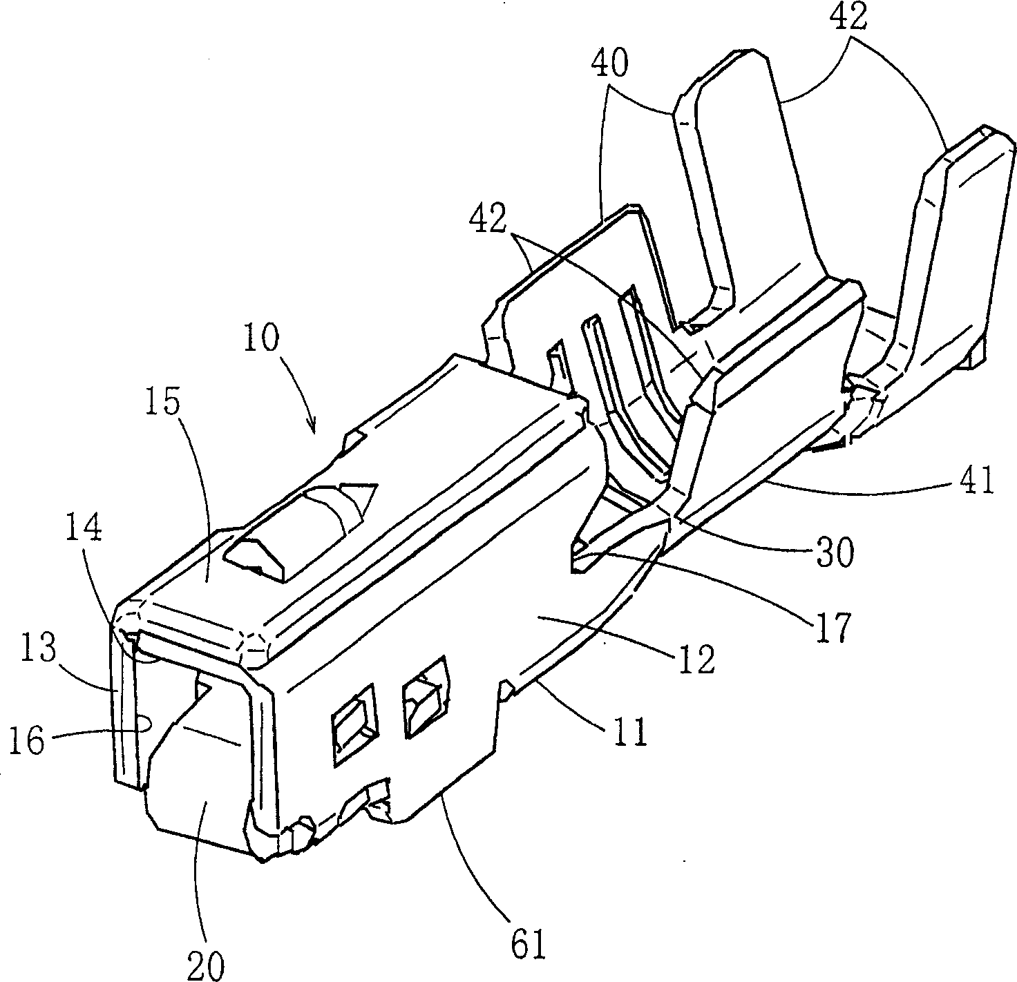
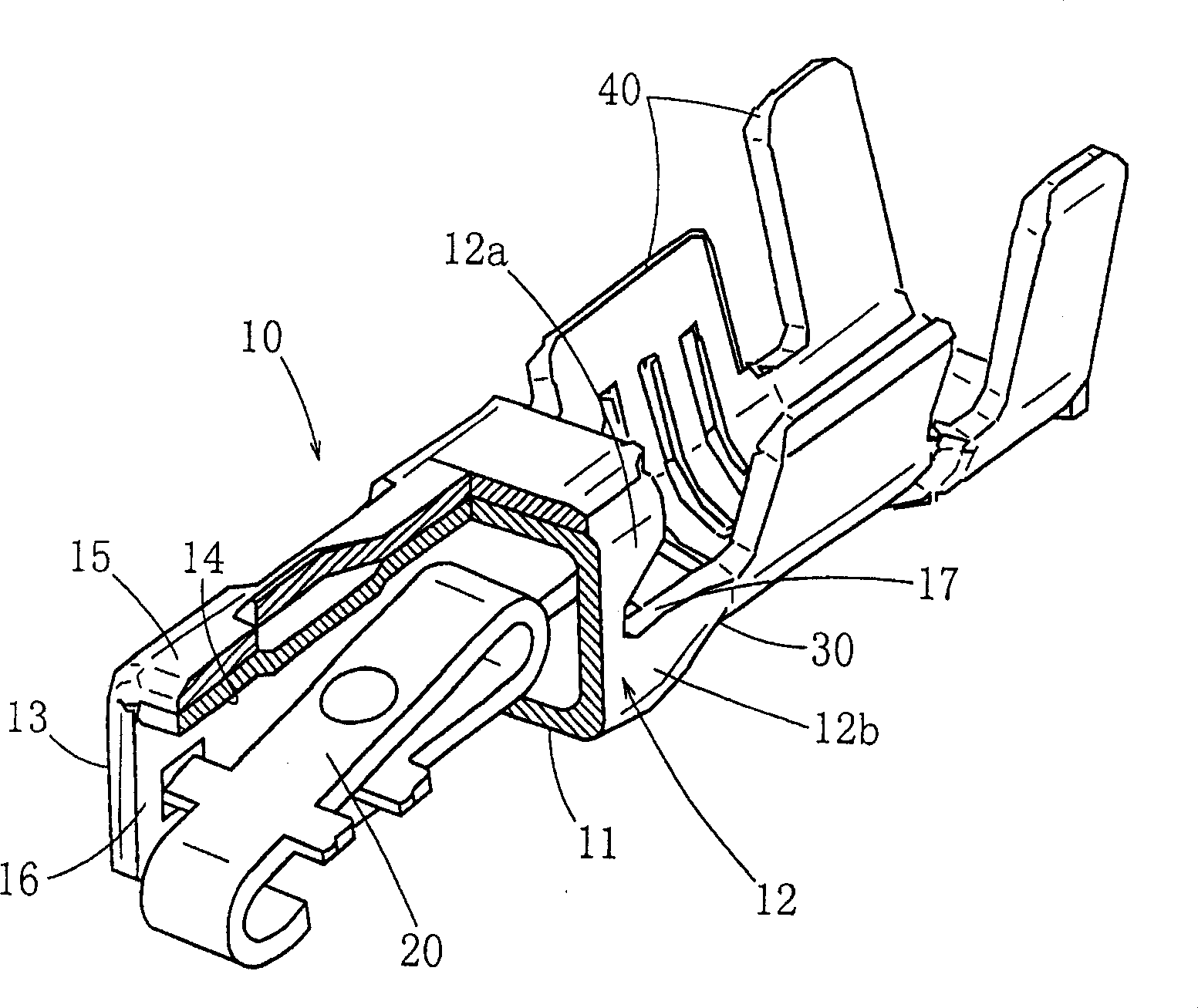
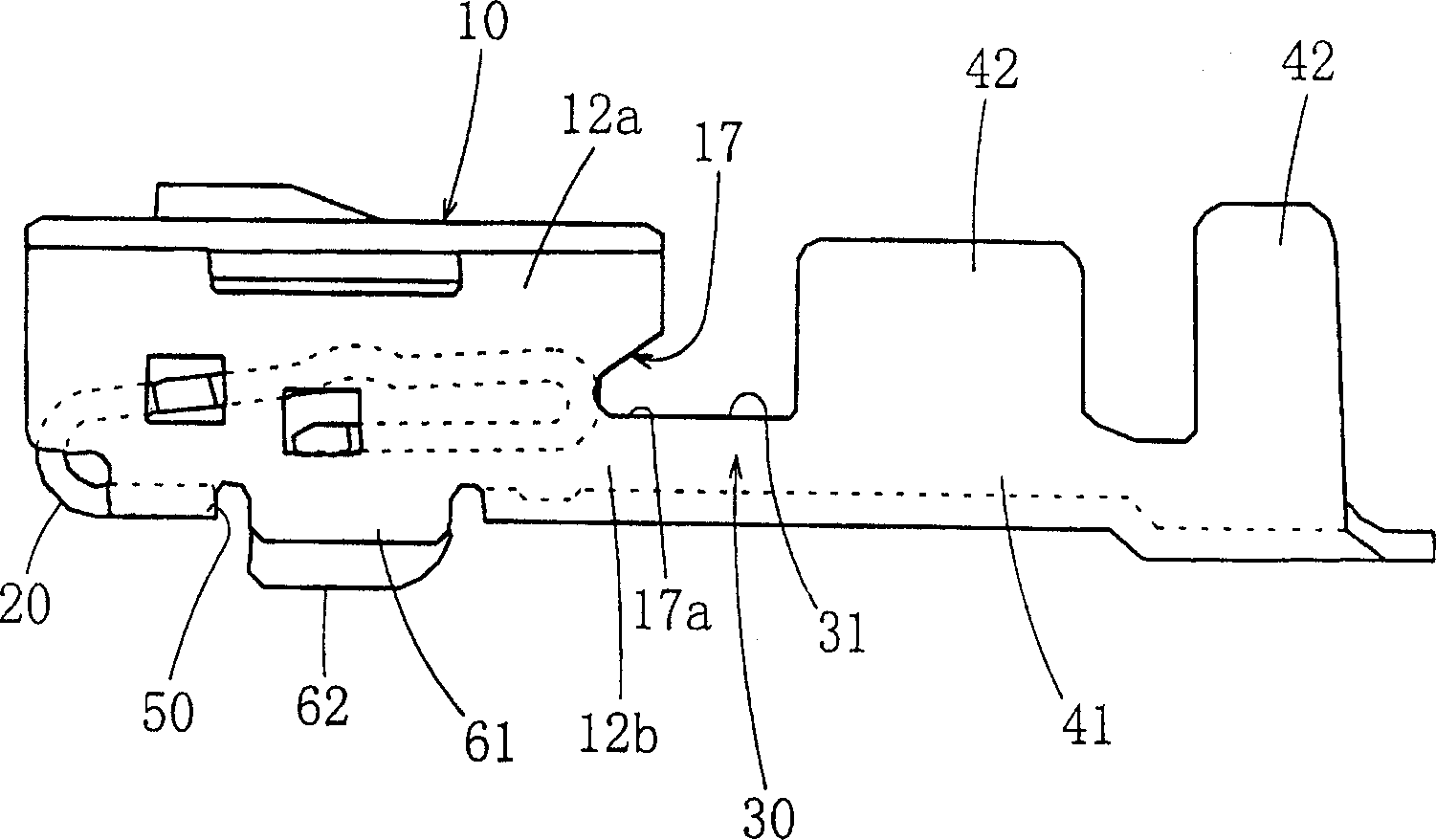
[0013] Embodiments of the present invention will be described below with reference to the drawings. Figure 1 ~ Figure 4 is the female crimp terminal of the shown example.

[0014] This female crimp terminal includes a cylindrical case 10 into which a male terminal is inserted through a front opening 16 , and a leaf spring 20 arranged inside the case 10 . The casing 10 has: a bottom wall portion 11, side wall portions 12, 13 standing up from both ends in the width direction of the bottom wall portion 11, and an upper wall extending sideways from the upper ends of the side wall portions 12, 13. Section 14, 15. The opening 16 is formed at the front end by each wall portion 1115 . In the case of this embodiment, the housing 10 is formed by bending a sheet. The first upper wall portion 14 extends sideways from the upper end of the side wall portion 12 on one side, and the second upper wall portion 15 extends sideways from the upper end of the side wall portion 13 on the other s...


PUM


Abstract

While securing the strength of the neck and securing the function of the leaf spring, bending of the upper parts of the side walls and expansion of the upper walls are prevented, and in turn, smooth insertion of the female crimp terminal into a cell of the housing is assured. As this allows shortening of the longitudinal length of the neck, the female crimp terminal can be compactified. The female crimp terminal comprising a tubular body (10), a leaf spring (20) being located inside the body (10) and being integrally formed on the front part of the body (10), a neck (30) being formed approximately into a U shape when seen in the longitudinal direction and being integrally formed on the lower parts (12b),(13b) of both side walls (12),(13) and the bottom wall (11) at the rear end of the body (10), and a barrel (40) being formed integrally into a U shape when seen in the longitudinal direction, being integrally formed on the neck (30) and having retainers (42) extending upward high above the neck (30), and a notch (17) is made in each side wall (12),(13) from the rear end of the body (10) so as to divide the side wall (12),(13) into an upper part (12a),(13a) and a lower part(12b),(13b).

Description

technical field [0001] The present invention relates to a female crimp terminal mounted on a housing of a female connector, and relates to a method for preventing deformation of the housing. Background technique [0002] In a conventionally known female crimp terminal, a leaf spring is provided inside a cylindrical housing through which a male terminal is inserted through a front opening, and the cylindrical housing portion is integrally provided in the housing via a neck portion. In the female crimp terminal disclosed in Japanese Patent Application Laid-Open No. 9-147950, the housing has: a bottom wall, side walls standing up from both ends in the width direction of the bottom wall, and side walls from the side walls. The upper wall portion extending from the upper end toward the side. The neck is formed in a substantially U-shape when viewed from the front-rear direction, and is integrally formed on the lower portion and the bottom wall portion of both side wall portions ...

Claims


Application Information

Patent Timeline
Patent Type & Authority Patents(China)
IPC IPC(8): H01R13/11H01R4/18H01R13/187
CPCH01R13/187H01R13/114H01R13/11
Inventor 陈平
Owner JST MFG CO LTD
Learn More