Optical system of projection display apparatus

A technology for optical systems and displays, applied in the field of optical systems with reflective light valves, can solve problems such as birefringence, large projection lens size, and large size

Inactive Publication Date: 2006-05-03
吕和 +1
View PDF2 Cites 0 Cited by
  • Summary
  • Abstract
  • Description
  • Claims
  • Application Information

AI Technical Summary

Problems solved by technology

The main disadvantage of this prior art optical system is: due to the angular dependence of the traditional polarized beam splitter, that is, the traditional polarized beam splitter produces polarized light in different directions for light incident on it at different angles. , resulting in serious uneven contrast and low contrast; the back focal length of the optical system is quite long, which leads to the problem that the brightness of the projected image it can provide is low or requires a larger projection lens size; and the The optical system involves severe birefringence, which seriously affects its projection quality
The main disadvantages of this existing projection display device are: the number of components is large, resulting in complex structure, high cost, and large size; the back focal length of the projection display device is quite long, resulting in low or Problems requiring larger projection lens sizes

Method used


Image

  • Optical system of projection display apparatus
  • Optical system of projection display apparatus
  • Optical system of projection display apparatus

Examples


Embodiment Construction

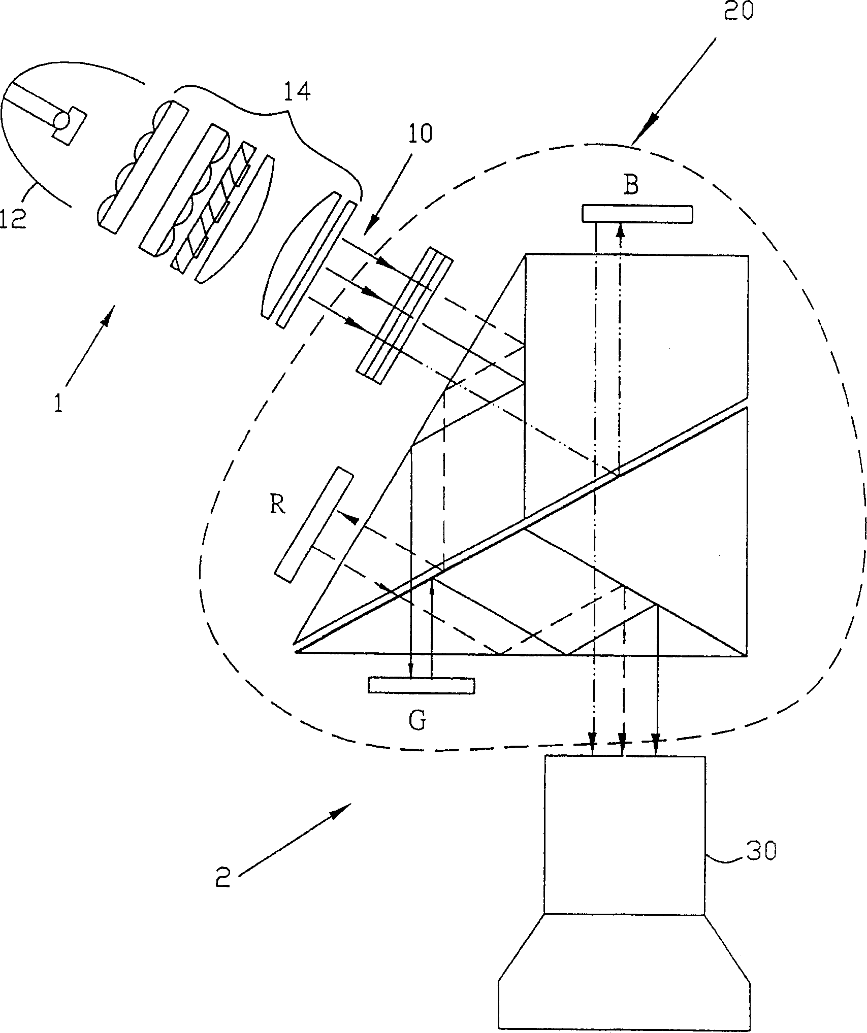
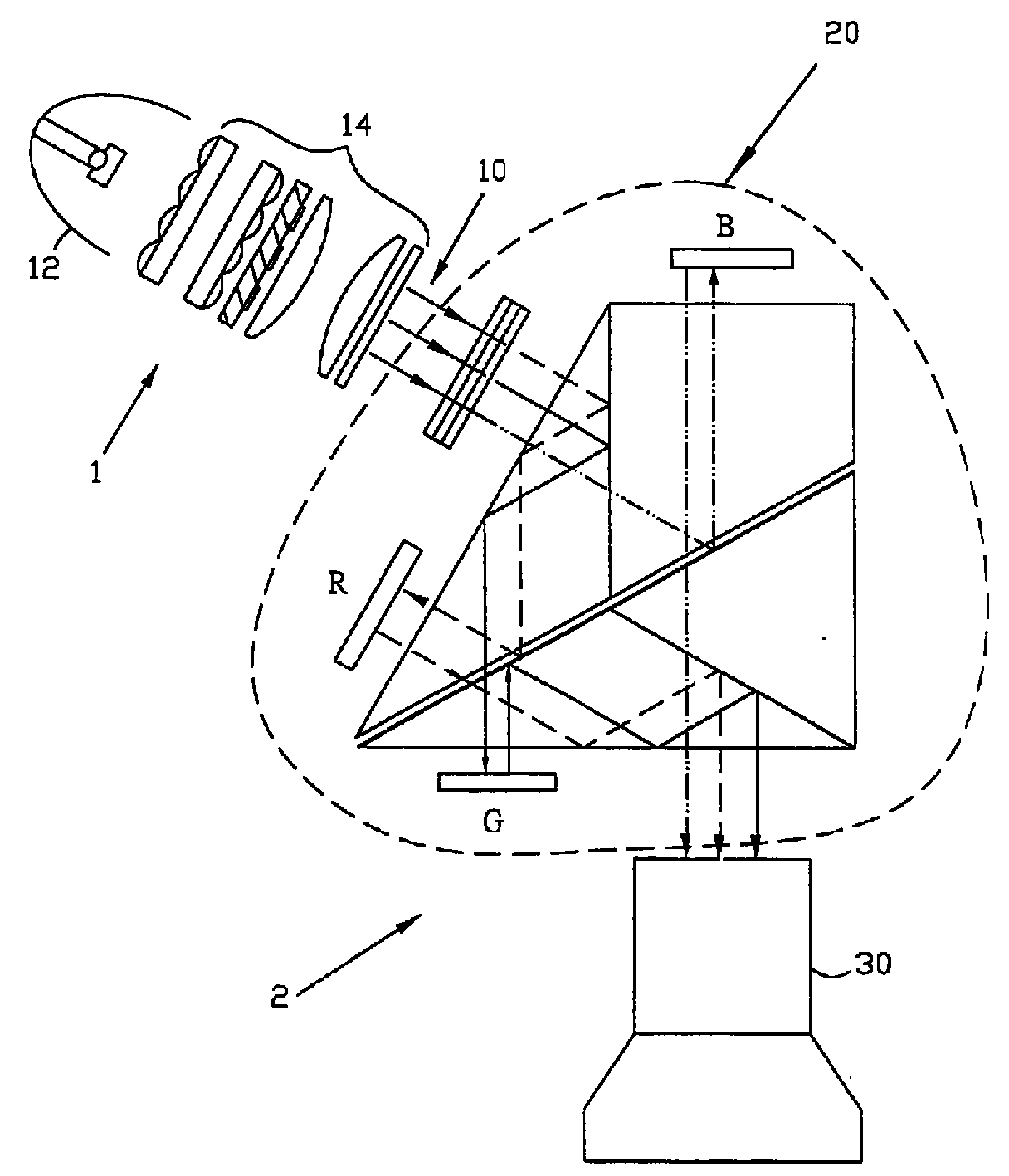
[0018] see figure 1 and figure 2 , an optical system of a projection display according to a preferred embodiment of the present invention includes an illumination system 1 and an imaging system 2 . The illumination system 1 includes a light source 12 for providing light; and an illumination module 14 for receiving the light from the light source 12 and outputting linearly polarized white light 10 .

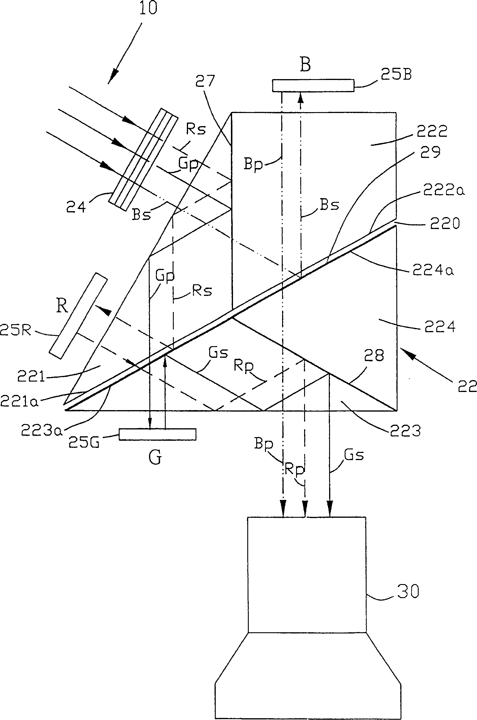
[0019] The imaging system 2 includes a color separation assembly 20 and a projection lens 30 . The color separation assembly 20 includes a prism assembly 22, a color selection component 24, and three reflective light valves 25R, 25G, 25B, and the reflective light valves 25R, 25G, 25B can reflect red light, green light, and Blue light, and change the polarization of each color light, that is, from P polarity to S polarity, or from S polarity to P polarity. In this case, see figure 2 , the light of P polarity means that the direction of the electric field vector of its electro...


PUM


Abstract

An optical system for a projection display, comprising a light source for providing light; an illumination module for receiving light from the light source and outputting linearly polarized white light; a color selection component for receiving the linearly polarized The white light of polarization, and output the first color light with the second polarization, the second color light of the first polarization, and the third color light of the second polarization; a prism assembly; a projection lens; and the first The first to the third reflective light valves can respectively be used to change the polarity of the first to the third color light from the prism assembly and reflect to the prism assembly, so as to enter the projection lens through the prism assembly .

Description

technical field [0001] The present invention relates to a projection display, in particular to an optical system with a reflective light valve in the projection display. Background technique [0002] In recent years, the importance of information visualization has been widely recognized, and the demand for projection displays has also increased rapidly. High display quality, low production cost, and product lightness are the main goals of research and development in this field. [0003] US Patent No. 5,777,789 by Chiu et al. discloses an optical system including a plurality of reflective light valves, a polarizing beam splitter, a plurality of color image combining prisms, an illumination system, and a screen. The main disadvantage of this prior art optical system is: due to the angular dependence of the conventional polarizing beam splitter, that is, the traditional polarizing beam splitter generates polarized light in different directions for ligh...

Claims


Application Information

Patent Timeline
Patent Type & Authority Patents(China)
IPC IPC(8): G02B27/18G02B27/28G02B27/10G02B5/04H04N9/31
Inventor 吕和
Owner 吕和
Why Eureka
Try Eureka