
Time division duplex receiving sending switch device

A technology of transmitting and receiving switches and time-division duplexing, which is applied in the direction of selection devices, electrical components, transmission systems, etc., can solve problems such as rising costs, achieve high power tolerance, achieve simple, and high isolation effects

Inactive Publication Date: 2006-06-07
ZTE CORP
View PDF1 Cites 0 Cited by
  • Summary
  • Abstract
  • Description
  • Claims
  • Application Information

AI Technical Summary

Problems solved by technology

Electronic switches, especially integrated IC switches, are generally used in applications where the power is less than 10W. In applications where the power is greater than 10W, the realization of electronic switches is technically difficult. Simply improving the power tolerance of the electronic switch itself will lead to a sharp increase in cost
When the power demand exceeds the possible power tolerance of the electronic switch, its circuit implementation will become a difficult problem to overcome. So far, no technology has been seen to solve this problem well.

Method used


Image

  • Time division duplex receiving sending switch device

Examples


Embodiment Construction

[0008] The present invention will be further described in detail below in conjunction with the accompanying drawings and embodiments.

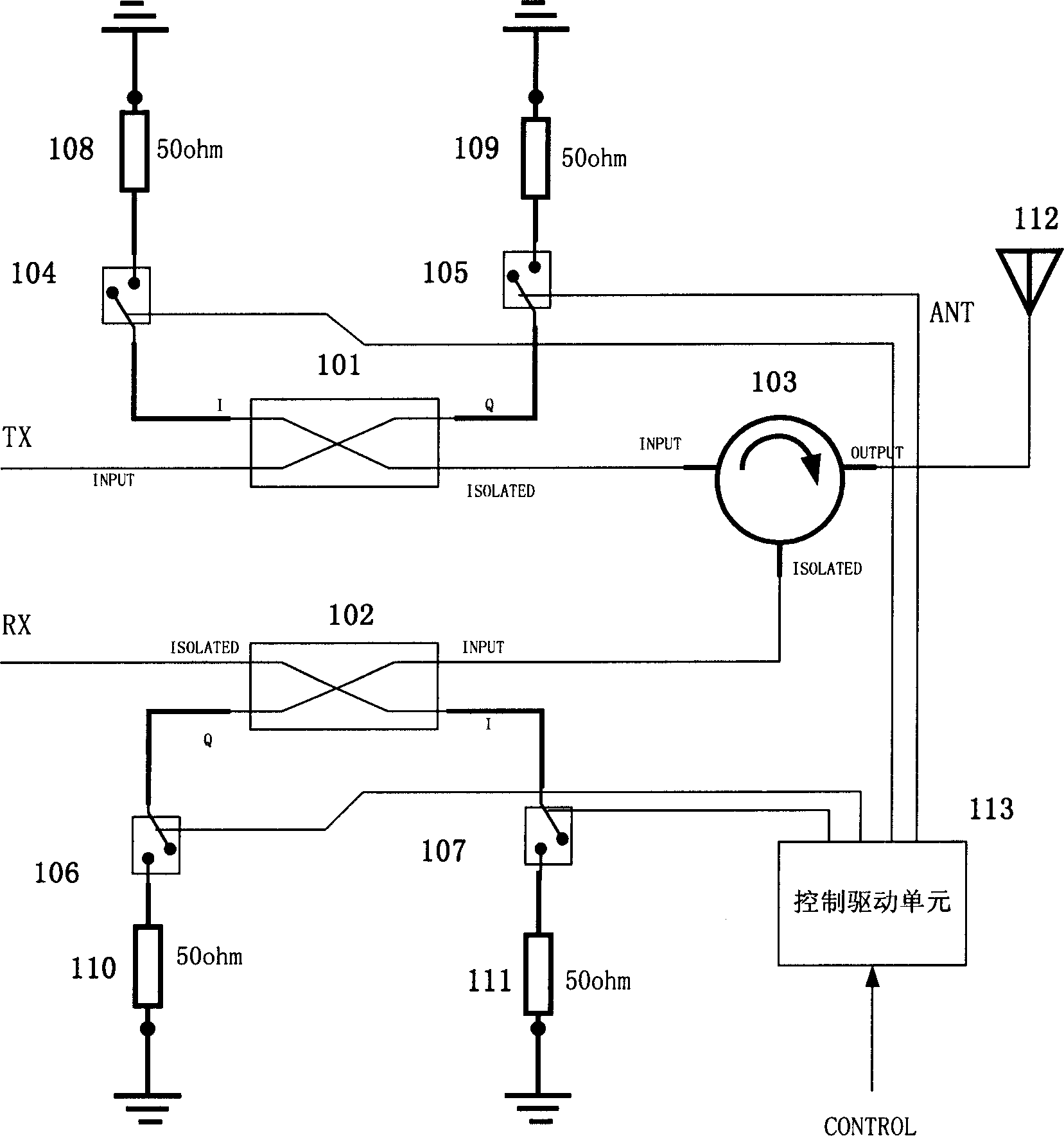
[0009] figure 1 It is a schematic diagram of the principle of the time-division duplex transceiver switch device proposed by the present invention. Such as figure 1 As shown, the device proposed by the inventor includes a circulator 103, a 3dB electric bridge 1, a 3dB electric bridge 2, an SPST electronic switch 1-4, a 50 ohm load 1-4, and a control drive unit 113; the control drive unit 113 uses Control and drive the opening and closing of the SPST electronic switch 1-4 according to the control signal; the INPUT terminal of the circulator 103 is connected to the ISOLATED terminal of the 3dB electric bridge 1 (101), and the ISOLATED terminal of the circulator 103 is connected to the 3dB electric bridge 2 ( 102) of the INPUT end, the OUTPUT end of the circulator 103 is externally connected to the antenna; the INPUT end of the 3dB electric bri...


PUM


Abstract

The device includes circline, 3dB electric bridge 1 and 2, 1-4 50 ohm loads of SPST electronic switch and control driving unit; based on control signal, control driving unit controls and drives on / off of SPST electronic switch; INPUT end of circline is connected to ISOLATED end of 3dB electric bridge 1; ISOLATED end is connected to INPUT end of 3dB electric bridge 2, OUTPUT end is connected to antenna, and a series of connection is made in the system. When system in emission state, control driving unit controls SPST electronic switch 1,2 to turn off, and SPST electronic switch 3,4 to turn on; When system in receive state, control driving unit controls SPST electronic switch 1,2 to turn on, and SPST electronic switch 3,4 to turn off. The advantages are high isolation and power tolerance, and simple implementation.

Description

technical field [0001] The invention relates to a switch device, in particular to a time division duplex transceiver switch device. technical background [0002] In the field of mobile communication, wireless devices generally adopt a duplex mode to realize sharing of transmitting and receiving antennas, and the duplex mode includes Frequency Division Duplex (FDD) and Time Division Duplex (TDD). For time-division duplex, radio frequency switches are generally used to realize duplex transmission and reception. The currently widely used radio frequency microwave transceiver switches generally use PIN diodes as the main device, and the PIN diodes of different paths are controlled by bias voltage to turn on and off to realize the transceiver function of the switch. A typical example is US Patent 20030119455 (Transmitting / Receiving Switch and Portable Terminal Unit). The transceiver switch described in this patent is to use the transmitting path to connect the diodes in series, ...

Claims


Application Information

Patent Timeline
Patent Type & Authority Patents(China)
IPC IPC(8): H04Q7/20H04Q7/32H04B1/40
Inventor 田其杨剑
Owner ZTE CORP
Learn More