Liquid releaser
A liquid discharge, integrated technology, applied in the direction of dispensing devices, packaging, transportation and packaging, etc., can solve the problems that the valve seat cannot be disconnected exactly, the liquid cannot be fully discharged, etc.
- Summary
- Abstract
- Description
- Claims
- Application Information
AI Technical Summary
Problems solved by technology
Method used
Image

Examples
no. 1 Embodiment
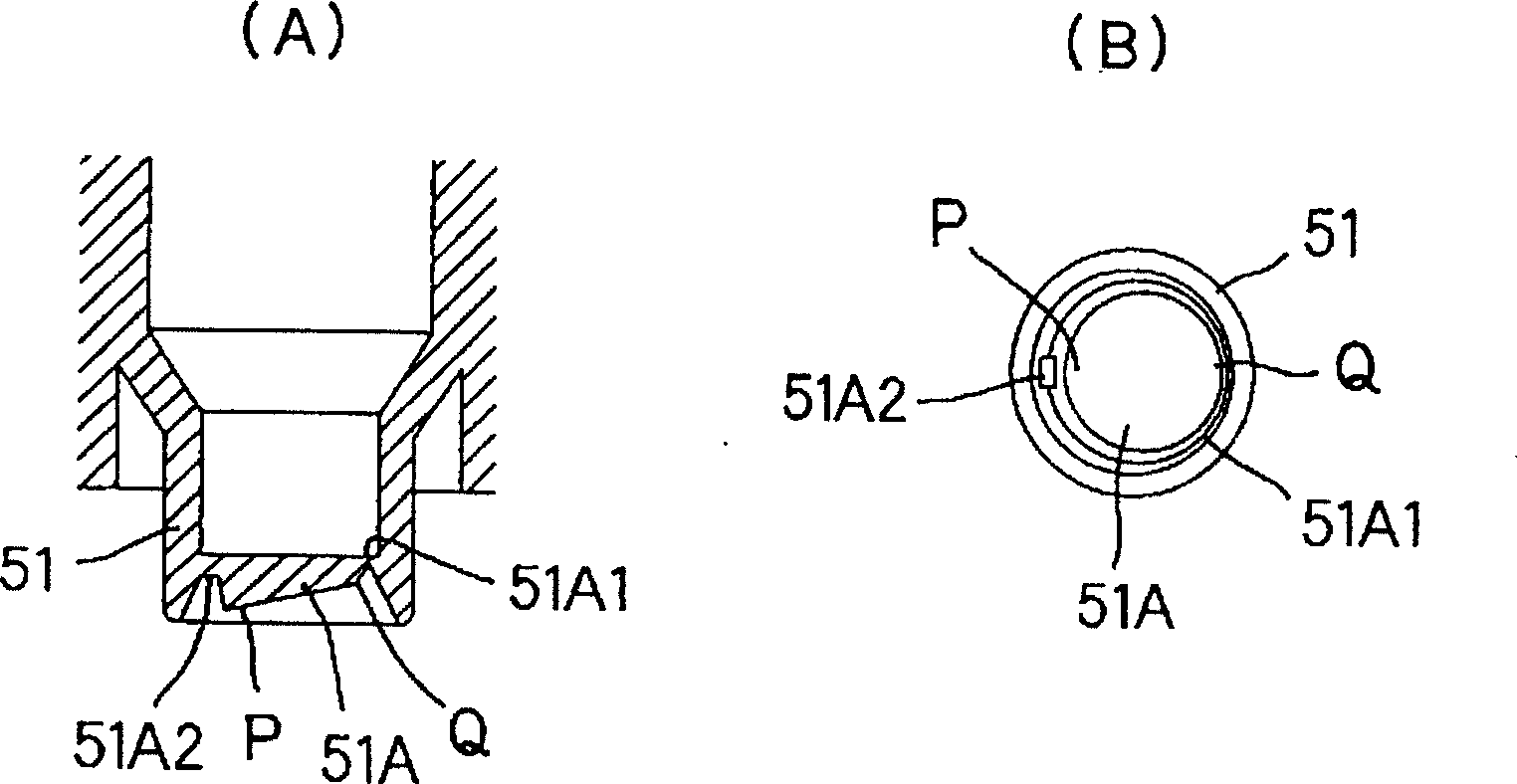
[0068] figure 2 Showing the first embodiment of the present invention, it is an enlarged view of a valve sealing body with an inclined bottom surface, wherein (A) is a cross-sectional view and (B) is a plan view.
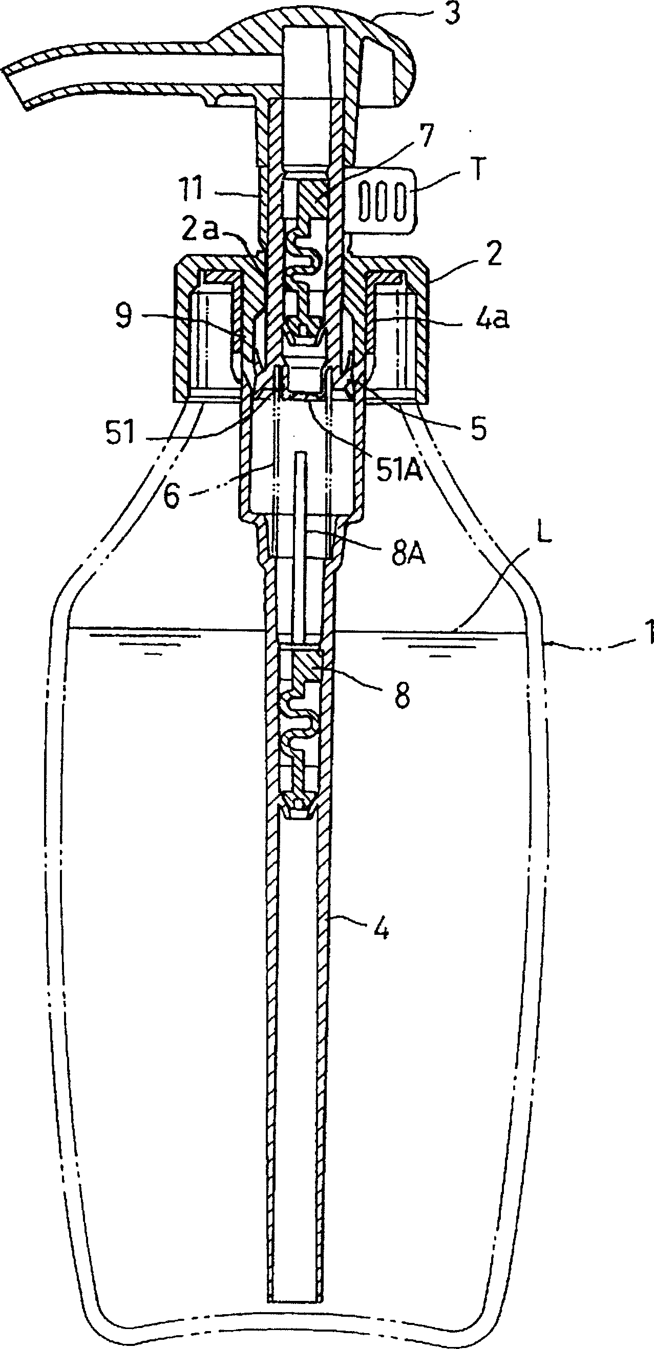
[0069] When the liquid discharge device is not in use, the valve sealing body 51A is coupled to the valve seat 51 through the thin wall portion 51A1 surrounding the outer periphery and the hinge portion 51A2 to close the opening of the valve seat 51 .
[0070] In this embodiment, the bottom surface of the valve sealing body 51A is inclined so that the hinge part side part P is downward and the opposite end Q is upward, and the wall is thicker at the P part and gradually becomes thinner toward the opposite end Q.
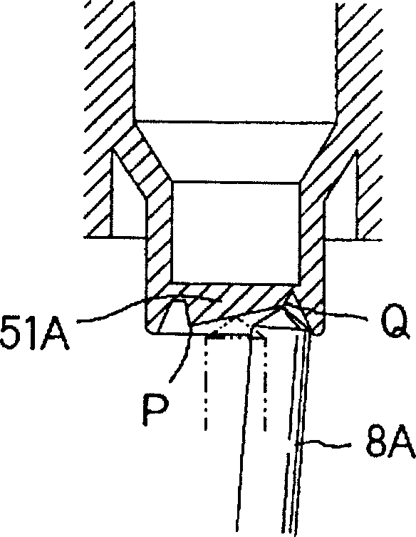
[0071] The enlarged view of the valve sealing body formed in this way in the state where the front end of the valve is pushed up is shown in Fig. image 3 Shows.
[0072] When the piston descends, the front end 8A of the valve is relatively pushed up, f...
no. 2 Embodiment
[0081] The inclination of the bottom surface of the valve sealing body can also be realized by inclining the entire valve sealing body.
[0082] Figure 5 An enlarged view showing a valve seal formed integrally inclined.
[0083] In this embodiment, the opening of the valve seat 51 including the valve sealing body 51A is formed in an inclined shape as a whole.
[0084] The hinge portion 51A2 is formed to connect the lowermost end of the valve seat 51 and the lowermost end portion P of the valve sealing body 51A.
[0085] The valve sealing body 51A has a constant thickness, and its bottom surface is gradually inclined upwardly from the lowermost end portion P toward the opposite end Q. As shown in FIG.
[0086] Incidentally, the thickness of the valve sealing body 51A does not have to be constant, and can be changed as appropriate.
[0087] With the valve sealing body formed in this way, as in the first embodiment, the front end of the valve is accurately guided to the oppos...
no. 3 Embodiment
[0089] The object of the present invention is to reliably break the thin-walled portion of the valve sealing body from a distance from the hinge portion, that is, from the vicinity of the opposite end.
[0090] As with the previous embodiments, it is not necessarily necessary that the front end of the valve push up on the opposite end itself, it can also be achieved by being arranged to push up as close as possible to the opposite end.
[0091] That is, a recess may be provided near the opposite end, and the front end of the valve may be guided to the recess.
[0092] Image 6 (A) is a cross-sectional view, and (B) is a plan view, which is an enlarged view showing a valve sealing body provided with a concave portion near the opposite end.
[0093] With this form, the front end of the valve inside the sleeve is reliably caught and stopped in the recess R. As shown in FIG.
[0094] Then, when the front end portion urges the concave portion R, it can be reliably broken from the...
PUM
 Abstract
Description
Claims
Application Information