Hermetic battery

a battery and hermetic technology, applied in the field of hermetic batteries, can solve the problems of expanding or breaking the battery case, the safety valve cannot function well, and the gas leakage is not easy to detect, so as to reduce thermal damage, reliably discharge the gas, and high safety

Active Publication Date: 2012-08-02
PANASONIC CORP
View PDF4 Cites 18 Cited by
  • Summary
  • Abstract
  • Description
  • Claims
  • Application Information

AI Technical Summary

Benefits of technology

[0015]The present invention can provide a highly safe hermetic battery which can reliably discharge the gas generated in the battery outside the battery, and can reduce thermal damage to a device in which the battery is inserted as much as possible.

Problems solved by technology

When an internal or external short circuit occurs, or the battery experiences abnormal heat generation or impact, charge / discharge reaction or chemical reaction occurs rapidly in the battery to cause rapid gas generation.
This may expand or break a battery case.
Thus, when the gas is generated faster than the gas is discharged, the safety valve cannot function well, and the pressure in the battery may increase to expand or break the battery case.
Thus, when the pressure in the battery has increased due to an abnormal event, it takes long time until the safety valve is operated, for which high temperature gas is generated to increase a temperature of the battery.
This may thermally damage a device in which the battery is inserted.

Method used


Image

  • Hermetic battery
  • Hermetic battery
  • Hermetic battery

Examples


Embodiment Construction

[0023]An embodiment of the present invention will be described below with reference to the drawings. The present invention is not limited to the following embodiment. Various modifications can be made to the embodiment within the scope of the present invention. The embodiment may be combined with other embodiments.

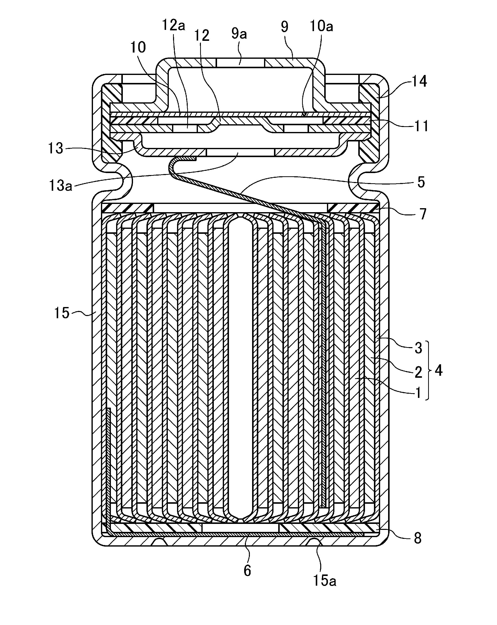
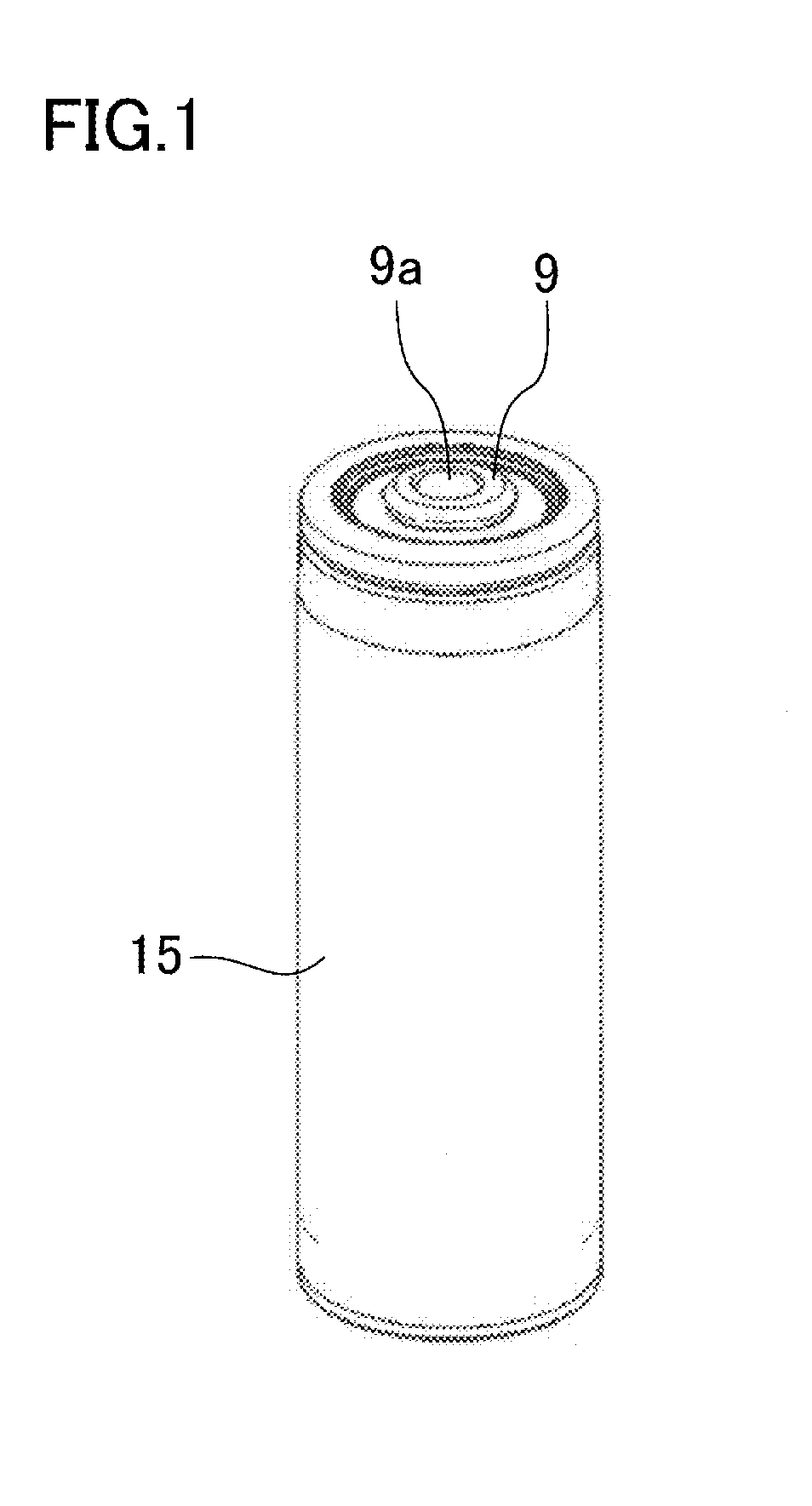
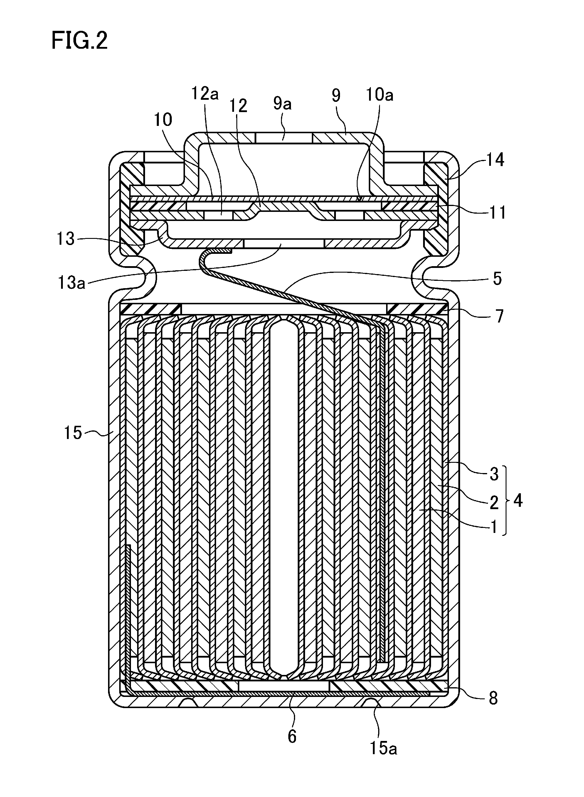
[0024]FIGS. 1-3 show a cylindrical nonaqueous electrolyte secondary battery according to an embodiment of the present invention. FIG. 1 is a perspective view, FIG. 2 is a cross-sectional view, and FIG. 3 is a bottom view.

[0025]As shown in FIG. 2, an electrode group 4 including a positive electrode 1 and a negative electrode 2 wound with a separator (a porous insulating layer) 3 interposed therebetween, and a nonaqueous electrolytic solution (not shown) are placed in a cylindrical battery case 15 having a closed end. Ring-shaped insulators 7 and 8 are arranged at upper and lower ends of the electrode group 4, respectively. The positive electrode 1 is connected to a filter 1...


PUM

PropertyMeasurementUnit
temperatureaaaaaaaaaa
operating pressureaaaaaaaaaa
pressureaaaaaaaaaa

Abstract

A hermetic battery including: a safety valve through which gas generated in the battery due to increase in pressure in the battery is discharged outside the battery, wherein the safety valve includes a first safety valve 9a, 10 which is operated at a first operating pressure, and a second safety valve 15a which is operated at a second operating pressure higher than the first operating pressure, a rate at which the gas is discharged while the second safety valve 15a is operated is higher than a rate at which the gas is discharged while the first safety valve 9a, 10 is operated, and the first safety valve 9a, 10 is closed at least while the second safety valve 15a is operated.

Description

TECHNICAL FIELD[0001]The present invention relates to hermetic batteries including a safety valve through which gas generated in a battery due to increase in pressure in the battery is discharged outside the battery.BACKGROUND ART[0002]Hermetic secondary batteries which can be charged and discharged have high energy density. When an internal or external short circuit occurs, or the battery experiences abnormal heat generation or impact, charge / discharge reaction or chemical reaction occurs rapidly in the battery to cause rapid gas generation. This may expand or break a battery case. For this reason, most of the hermetic batteries are provided with a safety valve (an explosion-proof mechanism) through which the gas generated in the battery is discharged outside the battery when a pressure in the battery reaches a predetermined value.[0003]As the safety valve provided in the hermetic battery, a sealing plate including a valve element which breaks when the pressure in the battery reach...

Claims


Application Information

Patent Timeline
Patent Type & Authority Applications(United States)
IPC IPC(8): H01M10/34H01M10/52H01M50/367
CPCY02E60/122Y02T10/7011H01M2/1252Y02E60/12H01M2/1241H01M2/12Y02E60/10H01M50/3425H01M50/367H01M10/02Y02T10/70H01M50/30
Inventor SHIMIZU, KEISUKEYOKOYAMA, TOMOHIKOFUJIKAWA, MASATOSUGITA, YASUNARI
Owner PANASONIC CORP
Why Eureka
Try Eureka