Airless dispensing pump container with an airtight push down type nozzle head

a technology of airtight push down and pump container, which is applied in the direction of packaging foodstuffs, instruments, packaged goods, etc., can solve the problems of content giving quality-change, easy oxidation and decay, and inability to implement a fixed amount of liquid discharge, etc., to achieve the effect of enhancing vacuum sealing function, and reducing the size of the nozzle hol

Inactive Publication Date: 2009-01-08
CHOI HEE JIN +2
View PDF6 Cites 20 Cited by
  • Summary
  • Abstract
  • Description
  • Claims
  • Application Information

AI Technical Summary

Benefits of technology

[0015]It is another object of the present invention to provide an airless dispensing pump container with an airtight push down type nozzle head capable of discharging a fixed amount of content in which a vacuum sealing function is enhanced in the whole structure of the present invention, and a content opening and closing valve member of a content discharge part provided at a nozzle head is automatically opened and closed, along with a reliable discharge of the content, and a reverse flow and leakage are prevented by improving the structure of the content pump piston which sucks and transfers the content. When the pump cylinder is slanted at a certain angle along with the content storing container or in case of the content having high viscosity, it is possible to improve the operation errors of the ball valve by providing an inventive structure for the ball valve support installed at the lower side of the stem.

Problems solved by technology

In the former case, since the external air (in particular, oxygen) resides in the content storing container at all times, the content may give quality-changes and may be easily oxidized and decayed.
So, the content of the collection chamber reverse-flows into the content storing container, so that it is impossible to implement a fixed discharge amount of the liquid since there is not any reverse flow prevention function.
In particular, the content has low viscosity, when the content is filled via the lower side of the container housing, and the lower side of the same is capped with the lower container, the container housing may have a certain level of pressure therein, so that the content may leak via the nozzle hole since the content reverse-flows.
So, it is impossible to implement a fixed amount of discharge.
Since the opening of the nozzle hole of the nozzle head is open all the time, the air may be inputted into the interior of the pump via the nozzle hole, so that the content may be solidified when contact with external air, whereby the content may not be smoothly discharged.
However, In the above conventional art 3, since large parts of the front end of the discharge valve is exposed due to the construction of the plug type discharge valve, a certain gap may be formed between the discharge valve and the valve hole when it receives an external pressure or the certain pressure difference occurs between the inner and outer atmospheres of the pump, so that certain foreign substance or air may easily penetrate into the inside of the pump or the content of the inside of the pump may be forced to pressurize the discharge valve, whereby the liquid can and may leak.
So, it is impossible to accurately control the flow rate and velocity of the content.
In the above art, the discharge valve should be engaged at the nozzle hole in a flow direction of the liquid, but the discharge valve is engaged at a slanted direction, so that the content that has a low viscosity may be discharged in not fixed one direction thereby causing many problems in use.
According to the conventional art 4, the content discharge hole of the nozzle tip is formed in a slit shape, so that it is difficult to keep a sealed state of the discharge hole.
However, when the pressure is not uniform, the discharge states of the content is also not uniform due to the discharge pressure, namely, it is slanted in one direction, so that it is impossible to obtain a uniform discharge direction in the above conventional art.

Method used


Image

  • Airless dispensing pump container with an airtight push down type nozzle head
  • Airless dispensing pump container with an airtight push down type nozzle head
  • Airless dispensing pump container with an airtight push down type nozzle head

Examples


Embodiment Construction

[0028]The preferred embodiment of the present invention will be described with reference to the accompanying drawings.

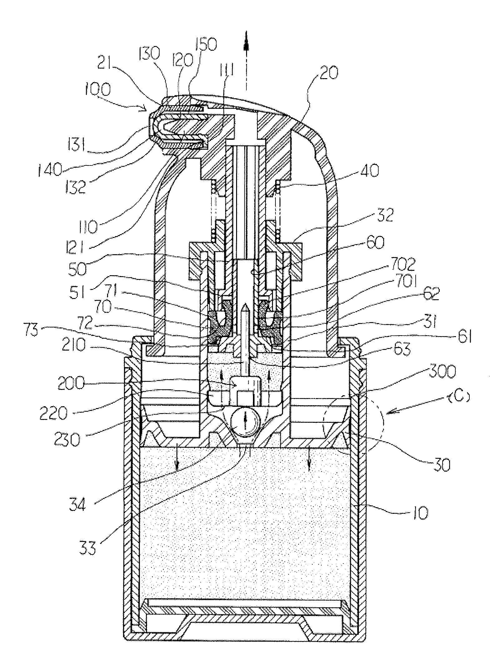
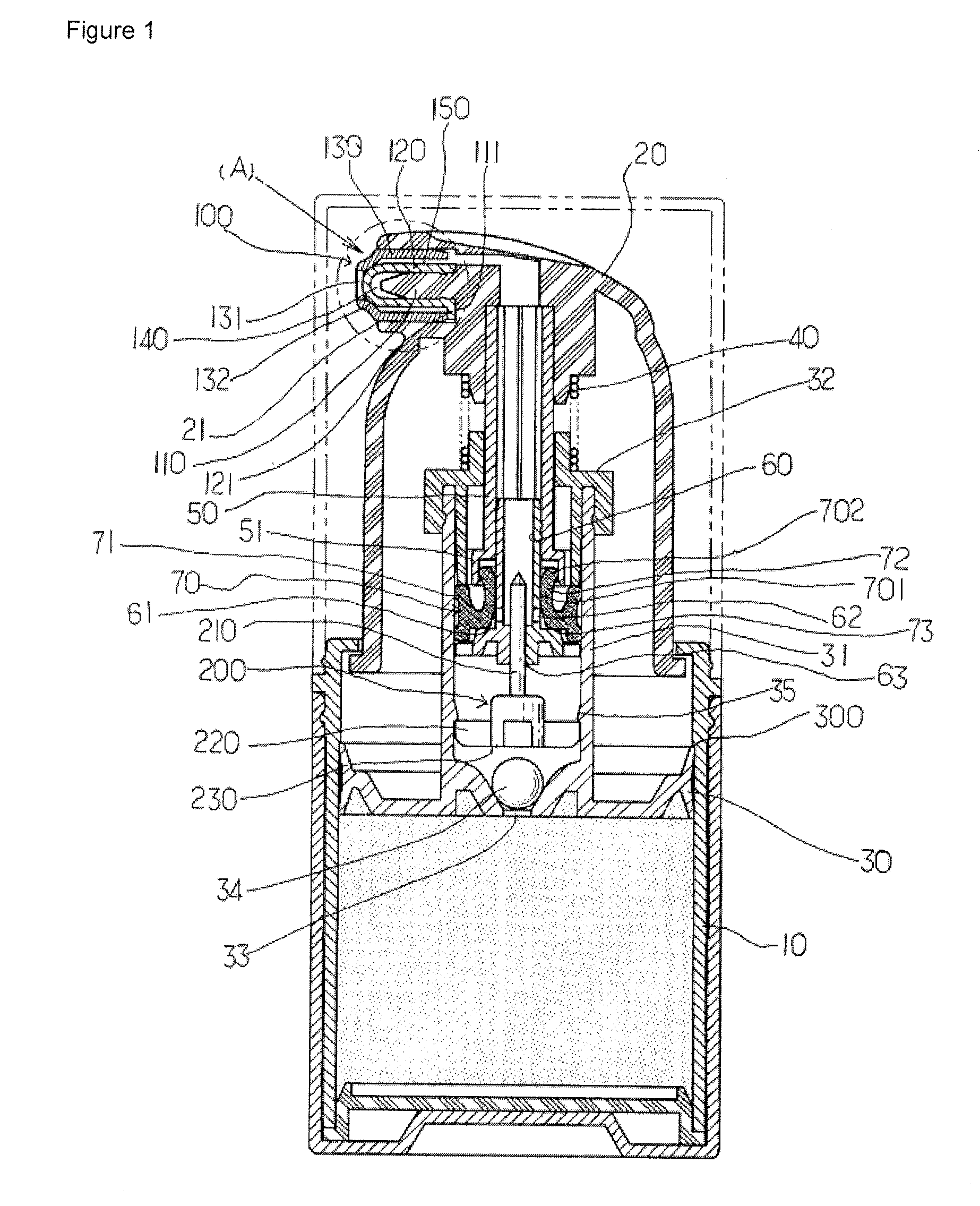
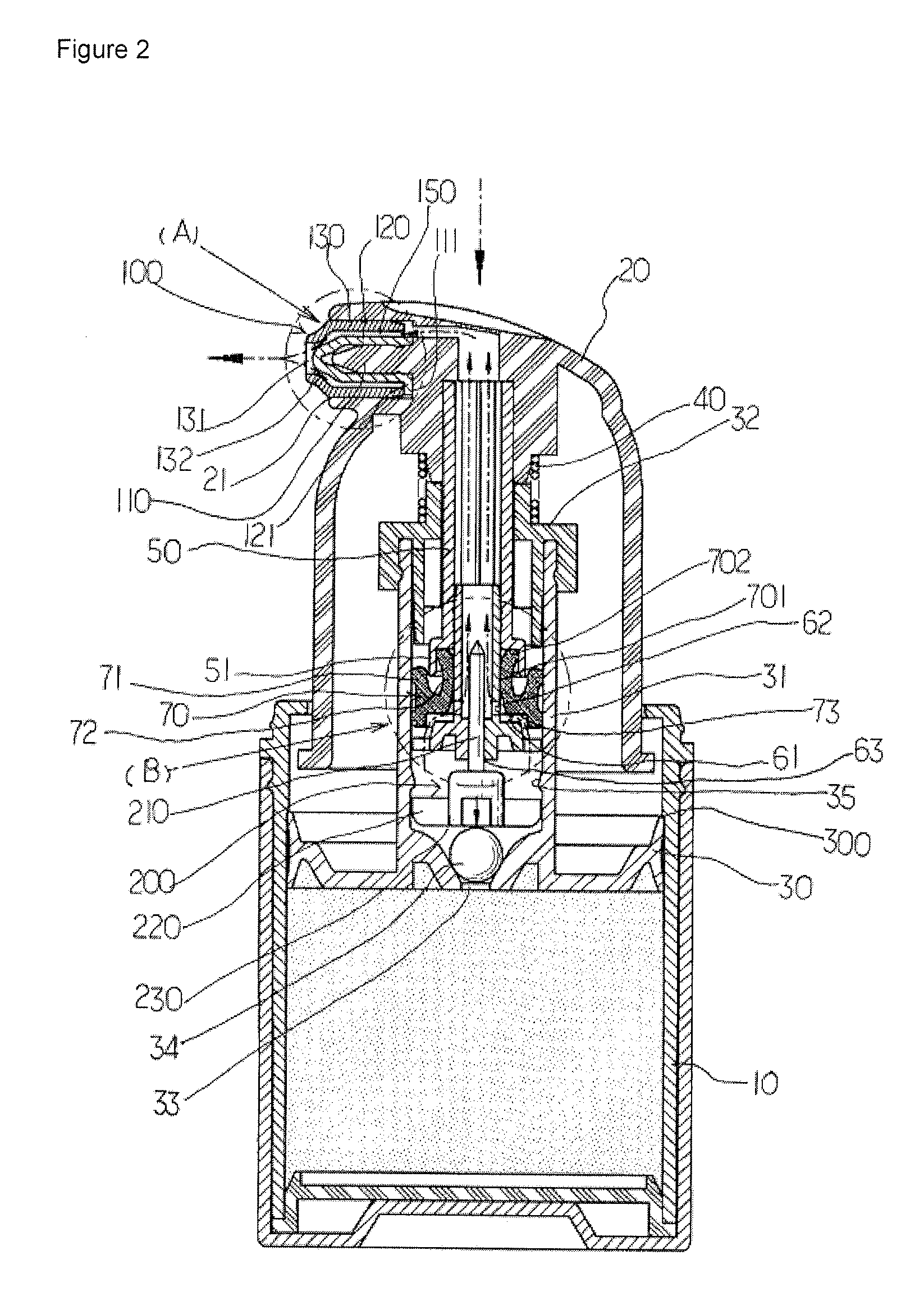
[0029]An airless dispensing pump container with an airtight nozzle head of a push down type comprises a content storing container 10 for storing liquid content therein, a nozzle head 20 which is assembled at an upper side of the content storing container 10 and has a nozzle engaging hole 21, a content compression piston 30 which is received in the content storing container 10 and is formed at a lower side, a pump cylinder 31 which is provided at a center portion, a pump cylinder cap 32 which is covered on an upper side of the pump cylinder 31, a first content inlet hole 33 which is provided at a lower center of the pump cylinder 31, a ball valve 34 which opens and closes the first content inlet hole 33, a ball valve support shoulder 35 provided at a lower inner wall of the pump cylinder 31, a nozzle head return spring 40 which is installed between the nozzle head 20 ...


PUM


Abstract

An airless dispensing pump container with an airtight push down type nozzle head is disclosed, which comprises a content discharge part which is installed at a nozzle engaging hole of the nozzle head; a ball valve support which is engaged at a lower side of the stem; and a content compression piston support shoulder which is provided at an inner upper wall of the content storing container. In the present invention, a vacuum sealing function is enhanced in the whole structure of the present invention, and a content opening and closing valve member of a content discharge part provided at a nozzle head is automatically opened and closed, along with a reliable discharge of the content, and a reverse flow and leakage are prevented by improving a structure of a content pump piston which sucks and transfers the content.

Description

TECHNICAL FIELD[0001]The present invention relates to an airless dispensing pump container with an airtight push down type nozzle head that is capable of discharging a fixed amount of content, while being engaged at a content storing container which is able to store various cosmetic contents.BACKGROUND ART[0002]Generally, in case of liquid cosmetic, a pump dispenser is used so as to easily discharge cosmetic stored in a content storing container based on a manual pumping operation by the user.[0003]The above pump dispenser for discharging stored liquid contents that is based on a pumping operation is made in various types. Here, a nozzle head up and down type pump dispenser container is more often generally used. According to a nozzle head up and down type, a vertical or horizontal nozzle head compresses the content pump piston connected to a nozzle head in a vertical or horizontal state by an external force thereby discharging its content. After the above operation is performed, it...

Claims


Application Information

Patent Timeline
Patent Type & Authority Applications(United States)
IPC IPC(8): G01F11/00B65D88/54
CPCA45D34/04A45D2200/056A45D2200/057B05B11/0051B05B11/007B05B11/0072B65D47/2075B05B11/02B05B11/3023B05B11/3066B05B11/3067B05B11/3074B05B11/0075B05B11/029B05B11/1023B05B11/1066B05B11/1067B05B11/1074A45D34/042
Inventor CHOI, HEE JINKWANG, YULEE, WON HEE
Owner CHOI HEE JIN
Why Eureka
Try Eureka