Ink-jet printer with air-discharge-flow assuring means

a technology of air-discharge flow and printer, which is applied in the field ofinkjet printer, can solve the problems of affecting the normal or proper printing operation, and the air-discharging device 303 constructed as described above suffers from another problem

Inactive Publication Date: 2005-09-29
BROTHER KOGYO KK
View PDF3 Cites 19 Cited by
  • Summary
  • Abstract
  • Description
  • Claims
  • Application Information

AI Technical Summary

Benefits of technology

[0023] According to the above-described third preferred form, the air-flow path from the air-inlet to the air-outlet is formed radially outwardly of the spring member that is disposed in the radially central portion of the valve chamber, so that, even when the spring member is in a compressed state, there is caused the discharge flow of the air within the valve chamber from the air-inlet toward the air-outlet, without being influenced by the state of the spring member. Therefore, the present arrangement is effective to prevent the discharge amount of the air from being varied in every air-purging operation.

Problems solved by technology

If the air is not discharged, the bubbles continue to be accumulated in the bubble accumulating chamber and consequently move to the printing head, disturbing a normal or proper printing operation.
Moreover, the air-discharging device 303 constructed as described above suffers from another problem.

Method used


Image

  • Ink-jet printer with air-discharge-flow assuring means
  • Ink-jet printer with air-discharge-flow assuring means
  • Ink-jet printer with air-discharge-flow assuring means

Examples


first embodiment

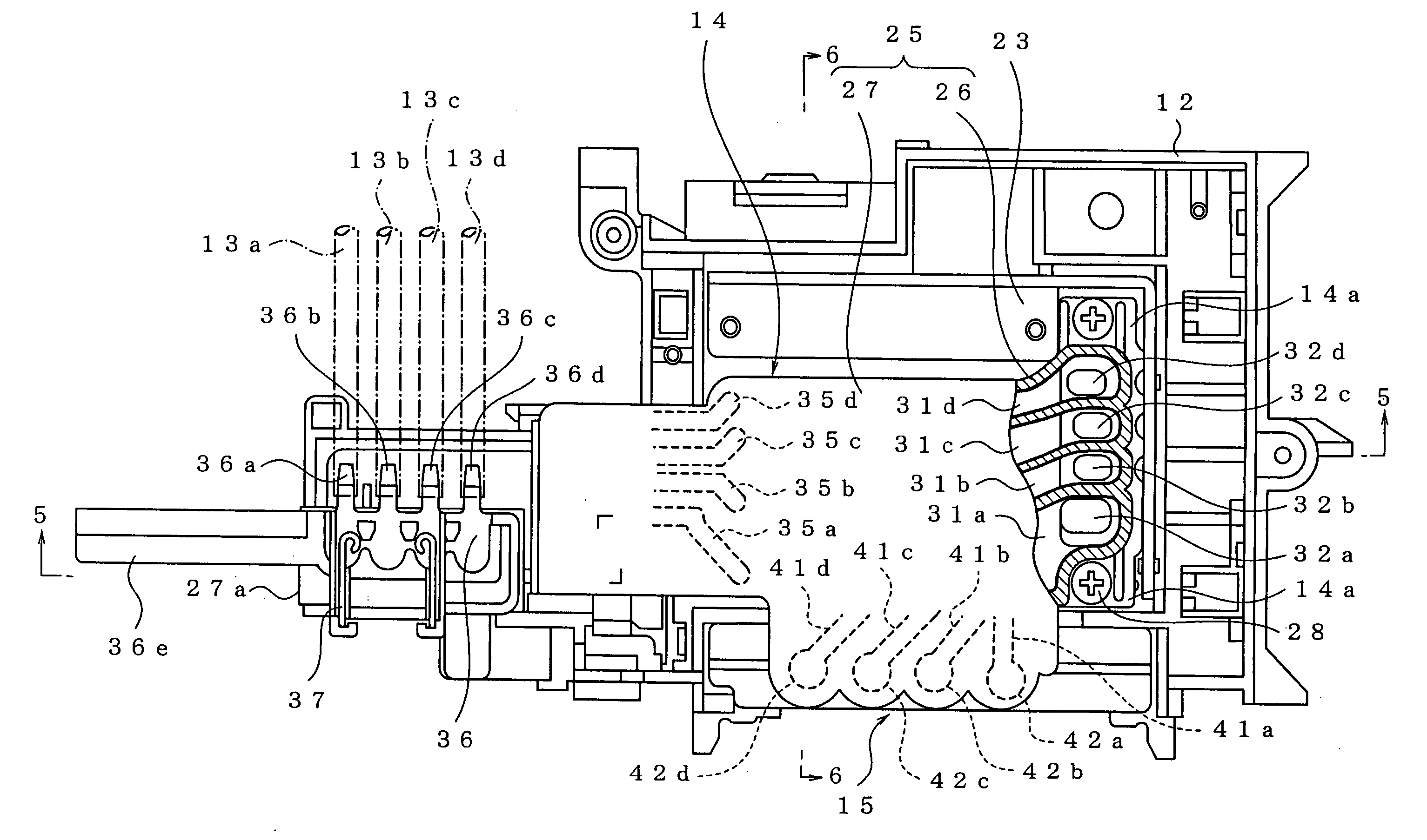
[0062] Referring next to FIGS. 6-9, there will be next explained in detail the air-discharging devices 15, constructed according to the invention, for discharging the bubbles (the air) accumulated in the bubble accumulating chambers 31a-31d of the buffer tank 14.

[0063] The four air-discharge holes 42a-42d formed on one side of the lower casing member 26 for the respective four inks extend in the vertical direction of the same 26 and are open at opposite ends thereof. As shown in FIG. 6, each air-discharge hole has an upper large-diameter portion and a lower small-diameter portion which communicate with each other via a communication opening. (In FIG. 6, while there is shown only the air-discharge hole 42d having the large-diameter portion 42A and the small-diameter portion 42B which communicate with each other via the communication opening 42C, the air-discharge holes 42a-42c have a structure similar to that of the air-discharge hole 42d.) Each air-discharge hole, in detail, the lar...

second embodiment

[0086] In this second embodiment, the air-discharging device 115 includes a valve member 144 shown in FIGS. 11A and 11B. Described more specifically, the valve member 144 includes: a valve portion having a large-diameter valve head 44a and a sealing member 144c whose outside diameter is substantially equal to that of the valve head 44a; and a rod portion 144b which is connected to the lower end of the valve head 44a and on which the sealing member 144c is inserted. The sealing member 144c is preferably a packing of rubber elastic body, for instance, and an O-ring is used in this embodiment. It is noted that the inside diameter of the sealing member 144c is not necessarily smaller than the outside diameter of the rod portion 144b. The rod portion 144b includes; a plurality of protruding portions 144f (five protruding portions in this embodiment) which are formed on the outer circumferential surface thereof such that the protruding portions extend in directions away from the center ax...

third embodiment

[0101] In this third embodiment, the air-discharge hole 42d includes an air-inlet 52 and an air-outlet (which is constituted by the communication opening 42C in this embodiment) which are located at the axially opposite ends of the large-diameter portion 42A, as shown in FIG. 14. The air-discharge hole 42d, in detail, the large-diameter portion 42A functions as a valve chamber in which a valve member 244 (which will be described) slides. In this embodiment, the air-discharge passage is constituted by including the air-discharge hole 42d, the air-inlet 52, and the communication opening 42C (the air-outlet). (In FIG. 14, while there is shown only the air-discharge hole 42d having the large-diameter portion 42A, the small-diameter portion 42B, and the communication opening 42C (the air-outlet), the air-discharge holes 42a-42c have a structure similar to that of the air-discharge hole 42d.)

[0102] The air-discharging device 215 includes the valve member 244 shown in FIGS. 15A and 15B. De...


PUM


Abstract

An ink-jet printer, including: a printing head for performing printing on a print medium by ejecting ink from nozzles; an ink tank for storing the ink to be supplied to the printing head; an ink passage through which the ink is supplied from the ink tank to the printing head; a buffer tank which stores the ink supplied through the ink passage; and an air-discharging device which discharges an air accumulated in the buffer tank through an air-discharge passage and which includes a valve member operable to open and close a communication opening that is provided in the air-discharge passage a part of which functions as a valve chamber and having: a valve portion which opens and closes the communication opening and which includes a sealing member; and a rod portion connected to the valve portion, wherein the air-discharging device further includes air-discharge-flow assuring means for assuring a discharge flow of the air flowing from the buffer tank through the air-discharge passage.

Description

[0001] This application is based on Japanese Patent Application Nos. 2004-092314, 2004-092315, and 2004-092316 filed on Mar. 26, 2004, the contents of which are incorporated hereinto by reference. BACKGROUND OF THE INVENTION [0002] 1. Field of the Invention [0003] The present invention relates to an ink-jet printer, in particular, an ink-jet printer capable of accumulating air bubbles generated in ink passages and discharging the air bubbles. [0004] 2. Discussion of Related Art [0005] To assure a reduction in the size (the thickness) of an ink-jet printer, there is a demand for a reduction in the size (the thickness) of a carriage of the printer, in other words, there is a demand that the ink-jet printer is constructed in such a way that an ink tank which accommodates ink is not installed on the carriage. To this end, the ink in the ink tank which is installed on a main body of the printer needs to be supplied, via an ink supply tube, to a printing head carried on the carriage. [000...

Claims


Application Information

Patent Timeline
Patent Type & Authority Applications(United States)
IPC IPC(8): B41J2/17B41J2/175
CPCB41J2/17513B41J2/17556B41J2/17523
Inventor USUI, TAKAMASATAKATA, MASAYUKI
Owner BROTHER KOGYO KK
Why Eureka
Try Eureka