Laminated dielectric filter

A filter and dielectric technology, applied in the field of laminated dielectric filters, can solve problems such as unfavorable filters

Inactive Publication Date: 2006-07-05
NGK INSULATORS LTD
View PDF1 Cites 0 Cited by
  • Summary
  • Abstract
  • Description
  • Claims
  • Application Information

AI Technical Summary

Problems solved by technology

Therefore, such a dielectric filter is not conducive to realizing a miniaturized filter

Method used


Image

  • Laminated dielectric filter
  • Laminated dielectric filter
  • Laminated dielectric filter

Examples


Embodiment Construction

[0082] Refer below Figure 1-29 Several illustrative embodiments of a laminated type dielectric filter according to the present invention are explained. In the following embodiments, the case where the input terminal is unbalanced and the output terminal is balanced is roughly explained. The present invention is also applicable to the case opposite to the above.

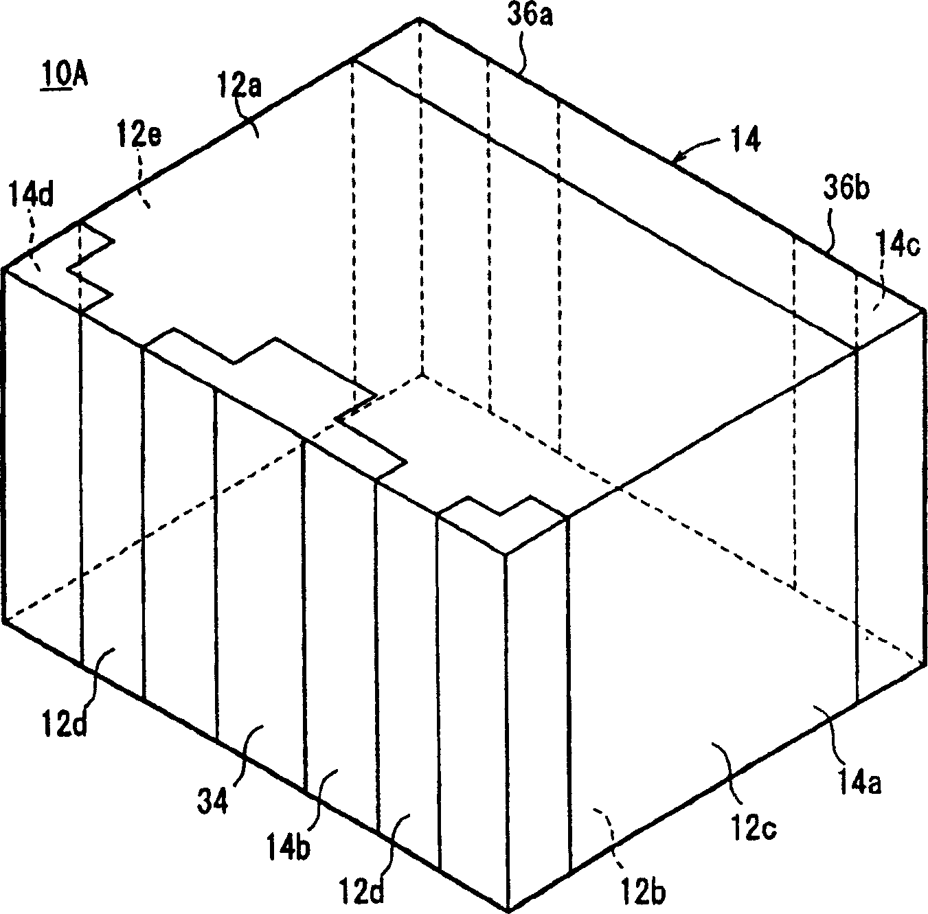
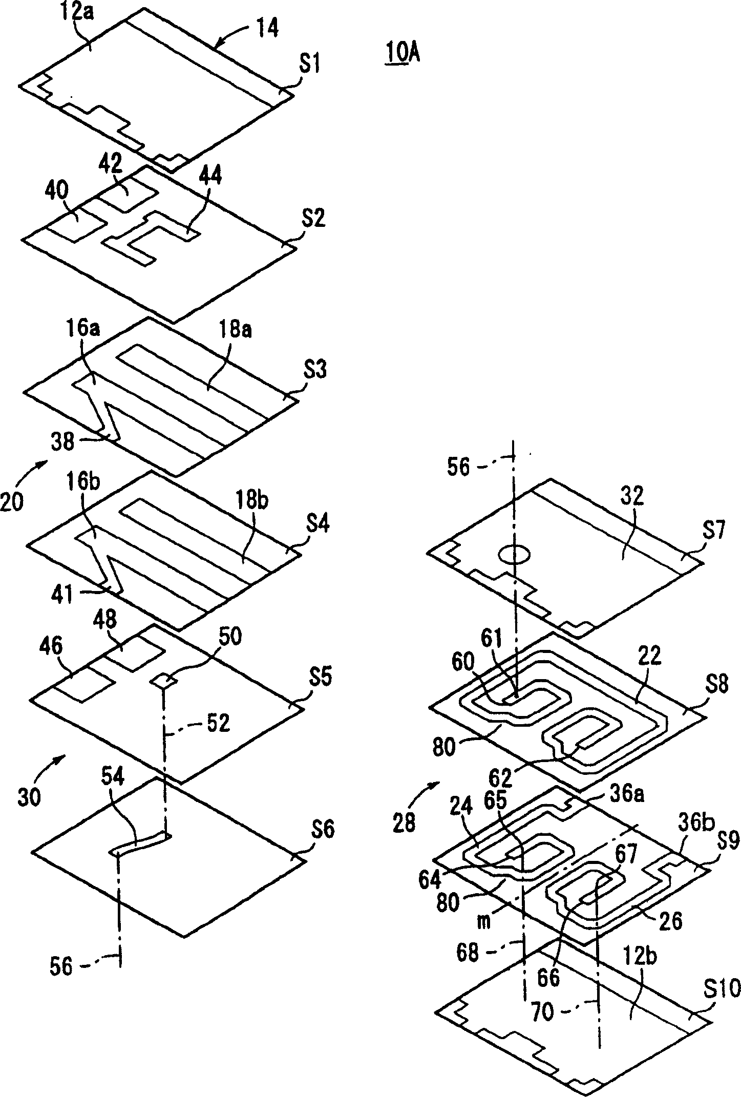
[0083] like figure 1 As shown, the laminated dielectric filter 10A of the first embodiment has a dielectric substrate 14 . The dielectric substrate 14 includes a plurality of dielectric layers (S1-S10, see figure 2 ). Ground electrodes 12a, 12b are formed on both main surfaces of the dielectric substrate 14 (the first main surface of the first dielectric layer S1 and the first main surface of the tenth dielectric layer S10).

[0084] like figure 2 As shown, a filter element 20 , an unbalanced-balanced conversion element (transition element 28 ), and a connection element 30 are disposed within the dielectric ...


PUM


Abstract

A stacked dielectric filter includes a filter section (20) which has first and second input side resonant electrodes (16a, 16b) and first and second output side resonant electrodes (18a, 18b) of two 1 / 4 wavelength resonators, a converting section (28) which has a plurality of strip lines (22, 24, 26), and a connecting section (30) which connects the filter section (20) and the converting section (28), wherein the filter section (20), the converting section (28), and the connecting section (30) are formed in a dielectric substrate (14). The filter section (20) is formed at an upper portion in the stacking direction of dielectric layers. The converting section (28) is formed at a lower portion in the stacking direction. The connecting section (30) is formed between the filter section (20) and the converting section (28).

Description

technical field [0001] The present invention relates to a laminated dielectric filter constituting a resonant circuit in the microwave frequency band of several hundred MHz to several GHz. More specifically, the present invention relates to a laminated dielectric filter that makes it possible to effectively miniaturize a communication device and an electronic device. Background of the invention [0002] In recent years, it has been extremely desired to realize a compact and thin high-frequency filter to be used in a wireless communication device. Therefore, it is indispensable to use a laminated dielectric filter. [0003] Generally, such as Figure 30 As shown, this laminated dielectric filter, for example, a laminated dielectric filter 400 using a 1 / 4 wavelength resonator has a plurality of resonant electrodes 402, 404, inner layer ground electrodes 406, 408, 410, 412, and a coupling adjustment electrode 414. Each of the plurality of resonant electrodes 402, 404 has one...

Claims


Application Information

Patent Timeline
Patent Type & Authority Patents(China)
IPC IPC(8): H01P1/20H01P1/203H01P1/205H01P3/08H01P5/10
CPCH01P1/20381
Inventor 水谷靖彦平井隆己门田和博阪太伸木村广伸
Owner NGK INSULATORS LTD
Why Eureka
Try Eureka