
Inflated tire and vulcanized metal die thereof

A technology for pneumatic tires and tires, which is applied to tire parts, tire treads/tread patterns, tires, etc., and can solve problems such as blade tilt, partial wear, and high stress

Inactive Publication Date: 2006-09-13
SUMITOMO RUBBER IND LTD
View PDF1 Cites 5 Cited by
  • Summary
  • Abstract
  • Description
  • Claims
  • Application Information

AI Technical Summary

Problems solved by technology

However, in US5,350,001, the pattern surface is not composed of parallelograms, and the shape of the opening edge will change along the depth direction, so the rigidity inside the block will be deviated, and the metal cannot be removed from the mold. The stress and moment generated on the surface, and will cause higher stress in local areas
In addition, as wear progresses, the shape of the opening edge changes, increasing the possibility of partial wear
In addition, when the blade is formed and processed, the blade will have a local inclination

Method used


Image

  • Inflated tire and vulcanized metal die thereof
  • Inflated tire and vulcanized metal die thereof
  • Inflated tire and vulcanized metal die thereof

Examples


Embodiment Construction

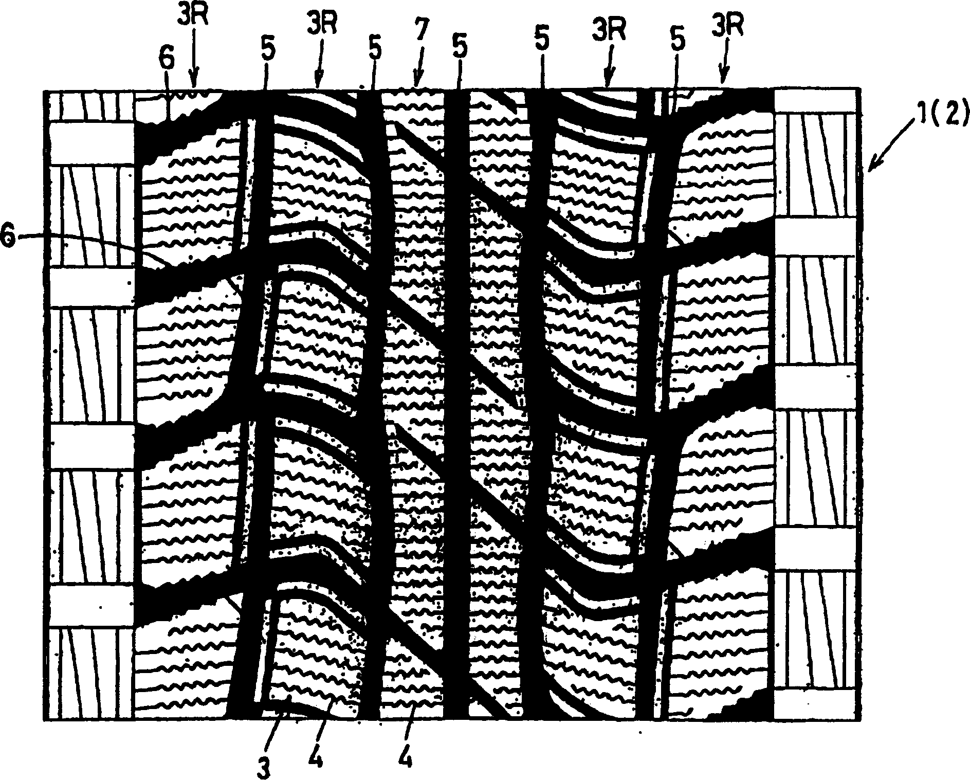
[0030] figure 1 It is a developed view of the tread pattern when the pneumatic tire of the present invention is formed as a studless tire for passenger vehicles.

[0031] exist figure 1 In the pneumatic tire 1 , a pattern 4 extending from one side edge of the block 3 to the other side edge is formed on a block 3 provided on a tire tread portion 2 .

[0032] In this example, by providing the tread portion 2 with longitudinal main grooves 5 extending in the circumferential direction of the tire and transverse main grooves 6 intersecting therewith, the tread portion 2 is divided into, for example, two ribs on the tire equator side. 7, and on both outer sides thereof, for example, four block rows 3R in which the blocks 3 are arranged at intervals in the circumferential direction. Meanwhile, on the aforementioned blocks 3 (in this example, on both the blocks 3 and the ribs 7 ), the patterns 4 are provided at intervals in the tire circumferential direction.

[0033] Secondly, on ...


PUM


Abstract

A pneumatic tire comprises a tread portion comprising tread elements each provided with a sipe (4), the sipe (4) having an open top end and a bottom, and in a range from the open top to a certain depth, a configuration of the sipe in a plane parallel with the tread face comprising a zigzag part oscillating in the longitudinal direction of the sipe in the course from the open top to said certain depth.

Description

technical field [0001] The present invention relates to a pneumatic tire and a vulcanized metal mold thereof which are very suitable for winter tires. By forming a pattern (cypisog) surface with a predetermined three-dimensional curved surface having three-dimensional concavities and convexities, excellent performance on ice can be exhibited, and the pattern formation can be suppressed. Damage such as falling off and bending of the blade. Background technique [0002] In winter tires such as snow tires and studless tires, in the prior art, a linear or zigzag pattern is formed on the squares formed on the tire tread to improve the flexibility of the square surface and increase adhesion. friction, and with the help of the scratching force (angular effect) on the road surface generated by the edge of the pattern, the driving performance on ice is ensured. [0003] And generally speaking, its driving performance on ice increases with the increase of the length and the number of...

Claims


Application Information

Patent Timeline
Patent Type & Authority Patents(China)
IPC IPC(8): B60C11/117B60C11/04B29C33/42B29C33/02B29C35/02B29L30/00B60C11/11B60C11/12
CPCB60C11/12B60C2011/1213B60C11/1218B29D2030/0613Y10S152/03
Inventor 岩村和光
Owner SUMITOMO RUBBER IND LTD
Learn More