Skip conveyor device of sheet-fed piece printing part

A technology for conveyors and workpieces, used in printing presses, general parts of printing machinery, printing, etc., can solve problems such as reduced operating efficiency, complicated changes in the peripheral speed of the second conveyor belt, and complicated changes.

Inactive Publication Date: 2006-09-20
ISHIKAWA SEISAKUSHO
View PDF1 Cites 0 Cited by
  • Summary
  • Abstract
  • Description
  • Claims
  • Application Information

AI Technical Summary

Problems solved by technology

Therefore, the peripheral speed of the second conveying belt changes complicatedly during the in and out operation, and becomes inconsistent with the peripheral speed of the first conveying belt.
In the case that the peripheral speeds of the two conveyor belts are not consistent, the conveyed corrugated cardboard cannot be guaranteed to move forward in a straight line. As a result, the corrugated cardboard passing through the second conveyor belt in and out is very likely to have printing errors in the subsequent process.
In addition, if in order to prevent this, the method of stopping the box making machine during the movement of the second conveyor belt in and out will result in a decrease in operating efficiency.
Also have as the prior art of above-mentioned existing gazette, enumerated the scheme that makes a conveyor belt (feeding belt) move back and forth as a whole, even in this example also becomes in addition to moving back and forth as a whole, will add the conveyor belt itself The peripheral speed of the peripheral speed also has the issue of complex changes

Method used


Image

  • Skip conveyor device of sheet-fed piece printing part
  • Skip conveyor device of sheet-fed piece printing part
  • Skip conveyor device of sheet-fed piece printing part

Examples


no. 1 Embodiment approach

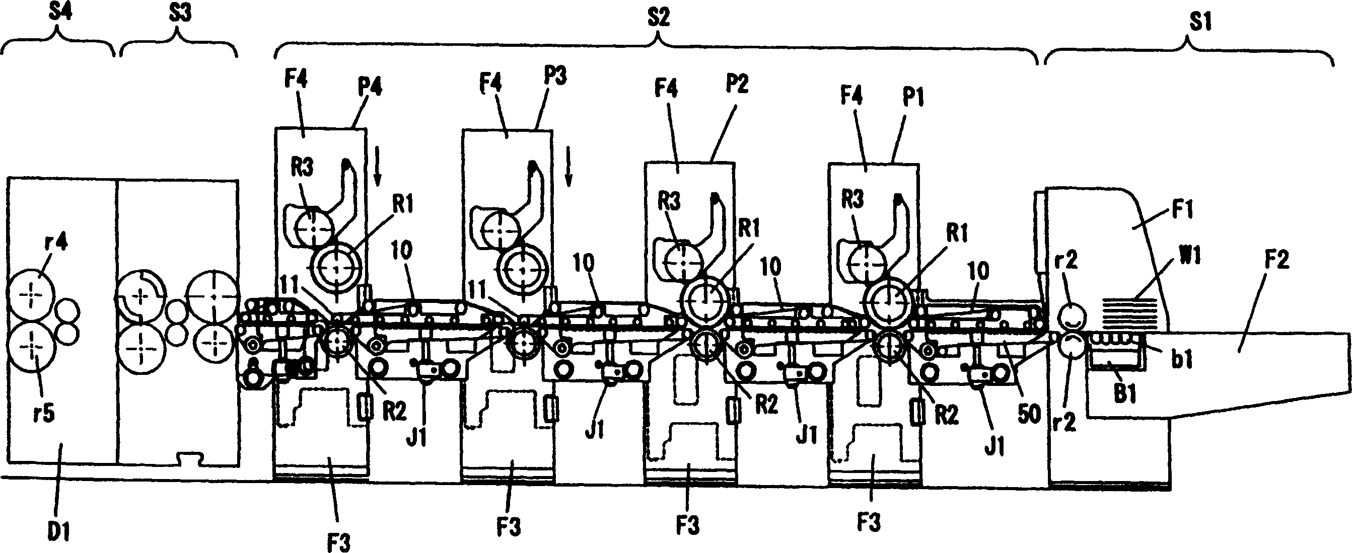
[0050] This embodiment is a corrugated box making machine ( figure 1 ). Below the upper feeding conveyor device 10, a lower feeding conveyor device 50 is arranged. The box making machine is connected in the order of paper feeding part 51, printing part 52, slotting part S3, punching part 54, folding part and delivery part from front to back. The single workpiece W1 after printing processing is cut groove and scribed in the slotting part S3, punches hand holes and air holes in the punching part S4, bends in the folding part, and is stacked and sent out in the sending part.

[0051] The general structure of the paper feeding part S1 is a frame F1 vertically erected at a certain distance from the left and right sides of the machine, and a feeding table F2 is horizontally arranged between the frames F1, and a suction box B1 composed of a plurality of guide rollers b1 is embedded on the feeding table F2 . In addition, a pair of upper and lower feeding rollers r2 is arranged late...

no. 2 Embodiment approach

[0075] This embodiment is also a way to keep the relationship of the peripheral speed of the feed belt with respect to the single workpiece constant, and is about another feeding conveyor device 30 ( Figure 7 , Figure 8 ). In this embodiment, the lower loading conveyor device 50 disposed below the loading conveyor device 30 has the same structure as that of the first embodiment.

[0076] Feeding conveyor device 30 has the feed belt 18 of the front end side that is contained between the front end pulley 11 and the middle pulley 19 and the feed belt 17 of the rear end side that is contained between the middle pulley 19 and the rear end pulley 15. Intermediate pulley 19 is the belt pulley of the double hanging method that can hang 2 feeding belts 17,18, and front end side feeding belt 18 and rear end side feeding belt 17 hang on the position that is equivalent to belt width apart. Further, the front-side feed belt 18 and the rear-side feed belt 17 are synchronously driven by ...


PUM


Abstract

To provide a feeder conveyor unit used in a printing part for sheet-form works arranged so that the payout / feed motion accuracy of each sheet-form work between a plurality of feeder conveyor units installed between a plurality of printing units in the in-line arrangement can be secured even in the case of the printing pass not capable of using the driving force of the printing unit. Each of the feeder conveyor units 10 is equipped with a front end pulley 11 to constitute the front end of the unit 10 when a feeder belt 17 is set on, a rear end pulley 15 to constitute the rear end of the unit 10, and a tension pulley 12 to maintain the tension of the feeder belt 17 within the specified range, in which only the front end pulley 11 is advanced to the rear end of the following conveyor unit 10 installed behind the printing unit P3 etc. which remains out of service without changing the position of the rear end pulley 15. (C)2004,JPO&NCIPI.

Description

technical field [0001] The present invention relates to the single-sheet workpieces that are respectively arranged between a plurality of printing units responsible for printing in various colors in the printing of single workpieces, and are used to transport the single workpieces of the printing units in the previous process to the printing units in the subsequent process. Invention of the feeding conveyor device for the printing part of the workpiece. Background technique [0002] The box making machine for corrugated box making is a single workpiece (corrugated cardboard for corrugated box making machine) that is supplied with raw materials from the upstream side, and it is processed sequentially, and finally the product that can be used directly after three-dimensional assembly is sent out. The so-called process equipment. The printing part in the box making machine is the process of single-color or multi-color printing on a single workpiece, and is the initial process ...

Claims


Application Information

Patent Timeline
Patent Type & Authority Patents(China)
IPC IPC(8): B41F21/00B65H5/02B65H29/16
CPCB65H2404/254
Inventor 宫前力也坂田博一竹田纯一
Owner ISHIKAWA SEISAKUSHO
Why Eureka
Try Eureka