
Device for spinning and winding at least one synthetic thread

A spinning device and spinning technology, which can be used in textiles and papermaking, bundling of newly ejected filaments, melt spinning, etc., can solve problems such as low control costs

Inactive Publication Date: 2008-01-02
SAURER GMBH & CO KG
View PDF9 Cites 0 Cited by
  • Summary
  • Abstract
  • Description
  • Claims
  • Application Information

AI Technical Summary

Problems solved by technology

[0004] The technical problem to be solved by the present invention is to constitute a device of the above-mentioned type in such a way that it can be realized at a very low control cost while maintaining a relatively high precision between a driven first godet roller and a driven first Small speed difference between two godets

Method used


Image

  • Device for spinning and winding at least one synthetic thread
  • Device for spinning and winding at least one synthetic thread

Examples


Embodiment Construction

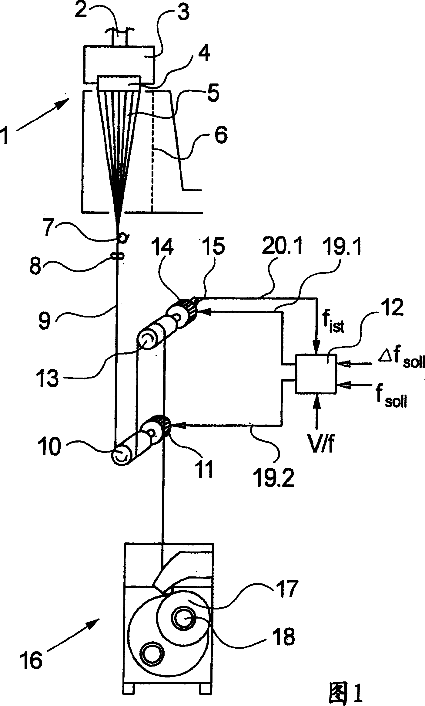
[0024] A schematic diagram of a first exemplary embodiment of the device according to the invention is shown schematically in FIG. 1 . The device according to the invention has a spinning device 1 for melt spinning. In the exemplary embodiment shown in FIG. 1 , the spinning device 1 consists of a spinning head 3 and a spinning nozzle 4 arranged on the underside of the spinning head 3 . The spinning head 3 includes spinning pumps (not shown here) and distribution lines, which are associated with a plurality of spinning nozzles. The spinneret 3 is here designed to be heatable. A polymer melt is conveyed via a melt conveying line 2 to a spinning head 3 . For the sake of clarity, only the thread flow of one thread is shown in the present embodiment.

[0025] The spinning nozzle 4 located on the underside of the spinning head 3 has a plurality of nozzle holes through which the polymer melt is extruded under pressure. As a result, a plurality of bundles of filaments are produced...


PUM


Abstract

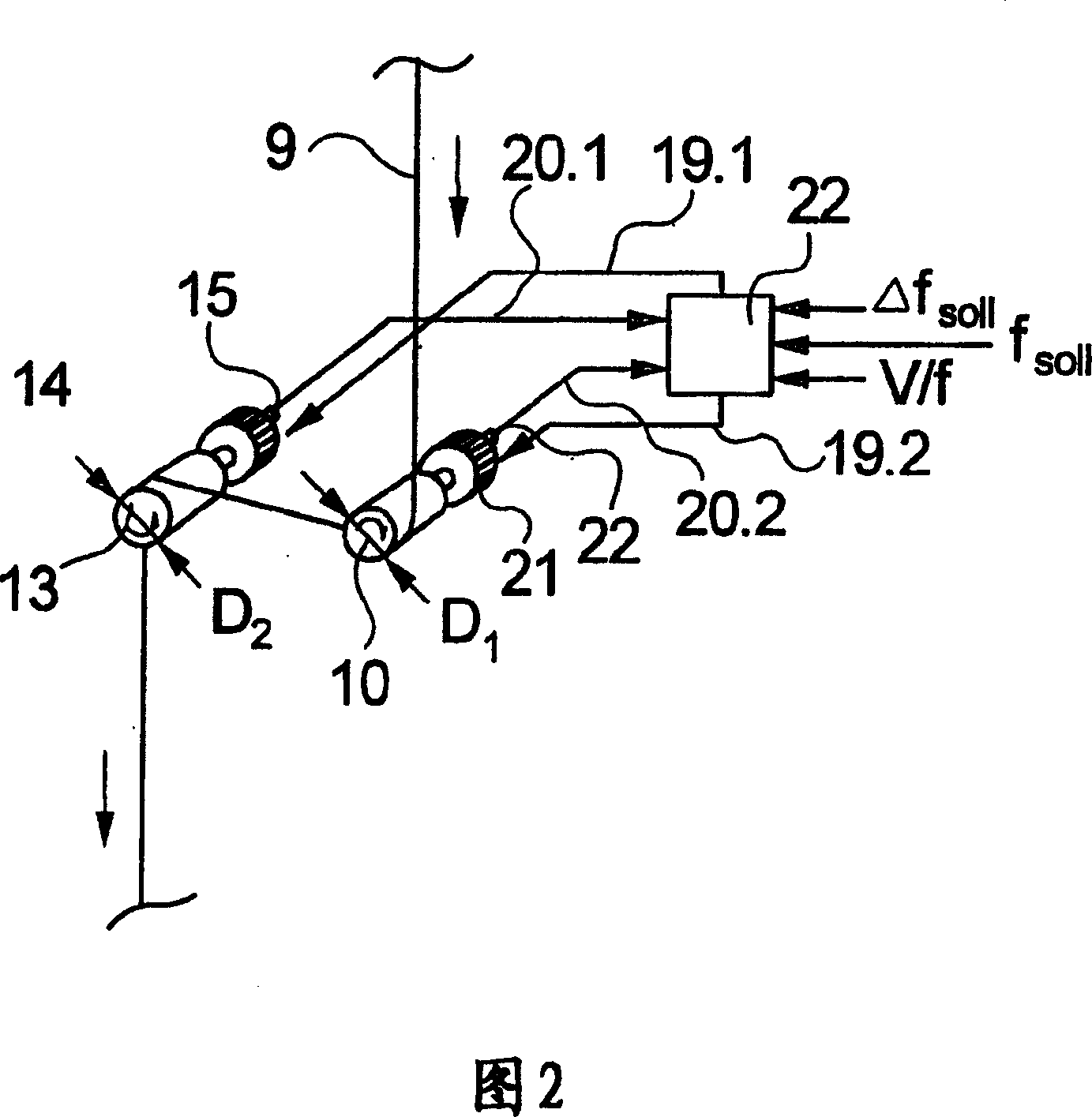
The take-off arrangement includes two rollers (10, 13) controlled from a single controller (12). One of the motors (14) is an asynchronous motor running with a small speed difference to the other due to electrical slip controlled by means of the voltage / frequency relationship. A sensor (15) provides a signal of the actual frequency so that the speed difference can be corrected. An Independent claim is also included for the process of controlling the speed difference of individually driven rollers by controlling the slip, one of the motors being an asynchronous motor. When the second roller (13) runs slightly slower than the first (10), e.g. for spinning partially oriented yarn with intermingling, the first motor (11) is a synchronous or a reluctance motor. Where the second roller has a higher surface speed, e.g. for spinning fully oriented yarn, the rollers are of different diameter to achieve a base difference, with fine control provided by electrical slip. In that case the first motor can be an electrically stiff asynchronous motor operating at constant slip.

Description

technical field [0001] The invention relates to a device for spinning and winding at least one synthetic thread. Background technique [0002] Such a device is known, for example, from DE 44 16 136 A1. [0003] For spinning and winding a synthetic yarn, known devices have a spinning device, a driven first godet and a driven second godet and a winding device. In this case, the filaments are drawn off via a first godet driven by an electric motor after the fused filaments have been ejected from the spinning nozzles of the spinning device. For this purpose, the first godet is partially wound with a wire. A second godet downstream of the first godet is likewise driven by an electric motor, wherein the speed difference between the first godet and the second godet is adjusted. The magnitude of the speed difference depends on the type of yarn to be produced. In the production of synthetic multifilament yarns from thermoplastic melts a distinction is mainly made between partiall...

Claims


Application Information

Patent Timeline
Patent Type & Authority Patents(China)
IPC IPC(8): D01D5/098H02P5/00D01D7/00D01D5/16D02J1/22
CPCD01D5/16D02J1/22D02J1/225Y02P70/62D01D7/00
Inventor 乌尔里希·恩德斯德特勒夫·舒尔茨
Owner SAURER GMBH & CO KG
Learn More