Method for manufacturing cross winding bobbin

A technology for cross-winding bobbins and bobbins. It is used in thin material handling, filament transportation, transportation and packaging, etc. It can solve the problem of reducing the receiving amount, and achieve convincing unwinding time, stable performance, and avoiding discontinuity. sexual effect

Inactive Publication Date: 2004-07-07
SAURER GERMANY GMBH & CO KG
View PDF1 Cites 4 Cited by
  • Summary
  • Abstract
  • Description
  • Claims
  • Application Information

AI Technical Summary

Problems solved by technology

[0015] The disadvantage of this double-conical cross-wound bobbin is that its receiving capacity is significantly reduced

Method used


Image

  • Method for manufacturing cross winding bobbin
  • Method for manufacturing cross winding bobbin
  • Method for manufacturing cross winding bobbin

Examples


Embodiment Construction

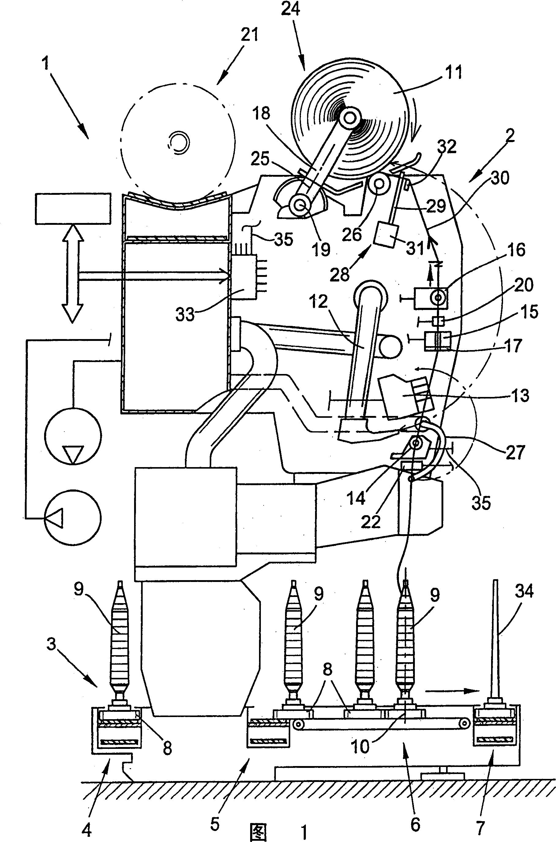
[0038] Fig. 1 schematically shows a spinning machine for manufacturing cross-winding bobbins. In this embodiment, it is an automatic cross-winding device, which is indicated as a whole by the symbol 1 in the figure. This kind of cross-winding automatic equipment usually has several identical stations 2 between its two end frames (not shown in the figure) (this is a well-known technology and is not shown in detail here). In ring spinning The bobbin 9 made on the machine is wound into a large cross-winding bobbin 11 at the station.

[0039] After being manufactured, the cross-wound bobbin 11 is transferred to a cross-wound bobbin conveying device 21 in the longitudinal direction of the machine, for example, by swinging the creel around the pendulum shaft 19, and is conveyed to a cross-wound bobbin conveying device 21 arranged at the end of the machine (Figure Not shown in) Package loading station or similar place.

[0040] In addition, this kind of cross-winding automatic equipment ...


PUM


Abstract

To produce a cross wound bobbin (11), at the workstation (2) of a bobbin winder (1), the yarn (30) is wound at the start of a winding cycle at a crossing angle to increase the density of the bobbin core. The crossing angle is increased significantly during the winding cycle, so that the density of the wound bobbin is reduced progressively outwards. The increased crossing angle acts against the yarn laying width, and the stroke movement of the reciprocating yarn guide (29) has a defined increase.

Description

Technical field [0001] The invention relates to a method of manufacturing a cross-wound bobbin as described in the preamble of claim 1. Background technique [0002] Such a cross-wound bobbin is formed on a cross-wound automatic device, for example. That is, in the station of the spinning machine, a relatively small small bobbin is wound into a large cross-wound bobbin, and the small bobbin is preferably spun on a ring spinning machine. In addition, the unevenness of the yarn is also detected during the winding process, so as to remove the bad yarn. [0003] In order to enable this kind of cross-wound bobbin to be processed in an orderly manner in the subsequent process, the cross-wound bobbin should have good unwinding properties. The unwinding properties of cross-wound bobbins may be affected by, for example, the way in which the yarn layers shift during manufacturing. There are two types of yarn displacement modes, the so-called "rough winding" and "fine winding". [0004] The...

Claims


Application Information

Patent Timeline
IPC IPC(8): B65H54/06B65H54/38B65H55/04
CPCB65H54/385B65H2701/31B65H54/06B65H55/04B65H2515/12
Inventor M・格里-莱费尔德
Owner SAURER GERMANY GMBH & CO KG
Why Eureka
Try Eureka