Modulation control scheme for power converters in photovoltaic system charge controllers

a photovoltaic system and charge controller technology, applied in electrochemical generators, secondary cell servicing/maintenance, transportation and packaging, etc., can solve the problems of non-mppt charge controllers artificially limit power production to a sub-optimal level, under-utilization of the maximum power output of pv arrays, and significant increase in voltage, so as to reduce the rms (root mean square) current value, minimize the efficiency of series-connected dual active bridges, and reduce current current valu

Active Publication Date: 2015-03-03
CUADROS CARLOS
View PDF2 Cites 35 Cited by
  • Summary
  • Abstract
  • Description
  • Claims
  • Application Information

AI Technical Summary

Benefits of technology

[0024]The invention is a modulation control scheme for a dual active bridge (DAB) DC to DC converter in a charge controller for photovoltaic systems composed of a photovoltaic (PV) array and a battery bank, wherein the charge controller controls charging of the battery bank with DC electricity produced by the (PV) array. In one preferred application of the invention, the modulation control scheme is employed in a dual active bridge (DAB) bidirectional DC to DC converter in a high voltage (HV) bidirectional maximum power point tracking (MPPT) charge controller for photovoltaic systems composed of a high voltage PV array, a battery bank and a high voltage DC load. The modulation control scheme maximizes the efficiency of a series-connected dual active bridge (DAB) bidirectional DC to DC converter implemented with MOSFETs as the switches in each full bridge of the converter. Conduction losses in the MOSFETs are minimized by reducing RMS (root mean square) current values and by employing synchronous rectification (reverse conduction of the MOSFETs). In addition, switching losses in the converter are minimized by achieving soft switching operation, and specifically by avoiding hard turn-off of the MOSFETs' intrinsic body diodes, either attaining zero-voltage switching (ZVS) when possible or resorting to zero-current switching (ZCS) without adding unnecessary switching actions. The modulation control scheme involves a minimum RMS current (M-RMS) mode of operation that minimizes conduction losses, and a full zero-voltage switching (F-ZVS) mode of operation that minimizes switching losses. The dual active bridge converter's operating range is divided into five cases or main operating regions in the M-RMS mode of operation, and into seven cases or main operating regions in the F-ZVS mode of operation. The cases or main operating regions are selected according to power levels and values of voltage differential, as well as the provision of appropriate transition or border operating regions between adjacent cases or main operating regions. This division is guided by minimization of the transformer's RMS current value, inclusion of both soft switching and synchronous rectification actions, when appropriate, avoidance of discontinuities in the converter's transfer characteristics, and allowance for straightforward, smooth control implementation. The modulation control scheme allows the dual active bridge DC to DC converter to operate for forward direction and reverse direction power flow, i.e. bidirectionally, in each mode of operation with minimized switching losses and minimized circulating energy (energy taken from the source, moved around the circuit and then fed back to the source), both as a standard-connection converter and as a series-connected converter, while taking advantage of the MOSFET's synchronous rectification capabilities to reduce conduction losses.

Problems solved by technology

If the photovoltaic system fails to produce enough electrical power to operate the connected end load, electricity is drawn from the utility grid to power the load.
Usually there is a mismatch between the output voltage of the PV array and the voltage required to charge the battery bank that results in under-utilization of the maximum power output from the PV array.
The reason for the mismatch is that most PV modules are rated to produce a nominal 12V under standard test conditions but, because they are designed for worse than standard test conditions, in actual fact they produce significantly more voltage.
Hence, non-MPPT charge controllers artificially limit power production to a sub-optimal level by constraining the PV array from operating at maximum output power.
In addition, lower battery voltage, as in the case of a highly discharged battery, will result in a greater charge current increase.
Some of the limitations to using a buck converter in MPPT charge controllers for photovoltaic systems include high peak currents and voltages with attendant high power losses, and increasing control problems as the input voltage increases.
While this MOSFET is “on”, the forward voltage drop of the body diode is limited to the “on” resistance of its transistor.
Conventional on-grid inverters, however, operate with high voltage PV arrays up to 600V, such that presently available MPPT charge controllers for photovoltaic systems are generally unsuitable for use in grid-connected photovoltaic systems due to their inability to handle the high voltage.
Consequently, switch power losses are significantly increased.
The MOSFET's intrinsic body diode exhibits poorer reverse recovery characteristics than a discrete power diode and, as a result, induces higher power losses than a discrete power diode when hard-switched off.
Outside the constrained range, however, zero-voltage switching is lost.
However, restrictions on the values for the normalized voltage conversion ratio preclude bidirectional operation under certain conditions.
However, this type of trapezoidal mode with zero-current during a portion of the switching semi-cycle is disadvantageous because it unnecessarily increases RMS current value and prevents zero-voltage switching operation in a certain range.
Song et al only considers voltage conversion rate values of strictly less than 1, and bidirectional operation for the same circuit design with this control scheme is not possible.
The control scheme proposed by Song et al can only assist the dual active bridge converter's efficiency in a very narrow range and for unidirectional operation.

Method used


Image

  • Modulation control scheme for power converters in photovoltaic system charge controllers
  • Modulation control scheme for power converters in photovoltaic system charge controllers
  • Modulation control scheme for power converters in photovoltaic system charge controllers

Examples


Embodiment Construction

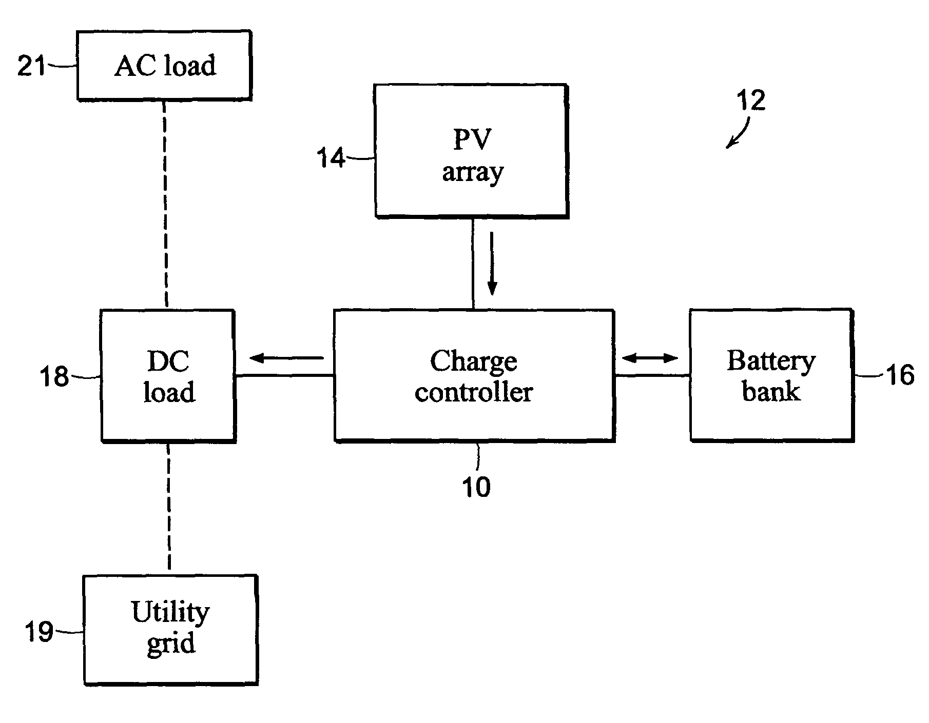
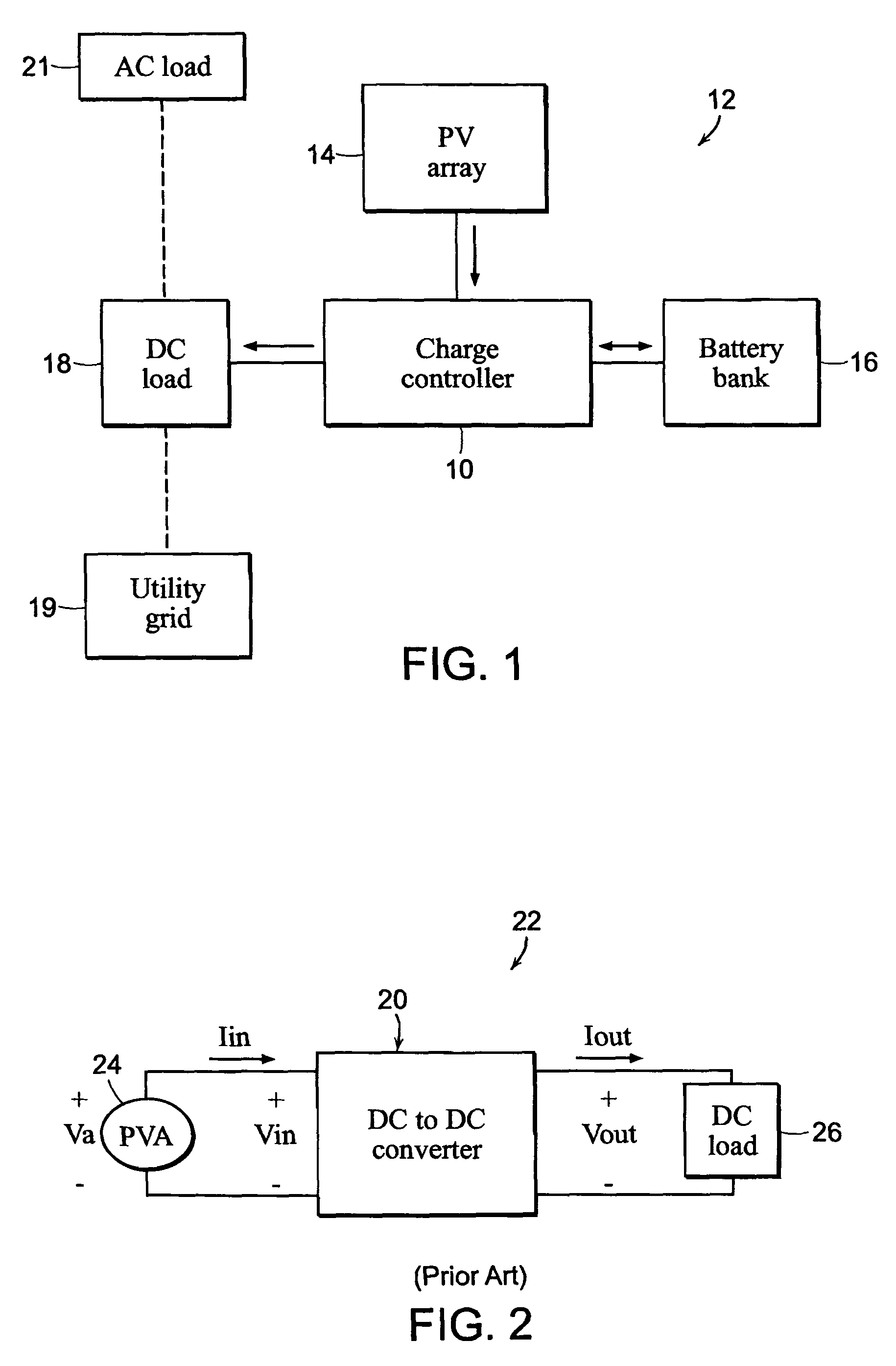
[0063]A high voltage (HV) bidirectional maximum power point tracking (MPPT) charge controller 10 is illustrated diagrammatically in FIG. 1 incorporated in a photovoltaic (PV) system 12 as disclosed in the co-pending prior U.S. patent application Ser. No. 12 / 896,427 previously incorporated herein by reference. The PV system 12 comprises a high voltage (HV) photovoltaic array 14 including one or more photovoltaic modules or panels, a battery bank 16 including one or more batteries, a high voltage DC load 18, and the high voltage bidirectional maximum power point tracking charge controller 10 electrically connected to the PV array 14, the battery bank 16 and the DC load 18. The high voltage DC load 18 may include an on-grid or grid-connected inverter for converting direct current (DC) electrical energy into alternating current (AC) electrical energy suitable for being supplied or fed into a public utility grid 19 connected to the on-grid inverter, as in the case where the PV system 12 ...


PUM


Abstract

A modulation control scheme for a series-connected dual active bridge (DAB) DC to DC converter in a maximum power point tracking charge controller used in a photovoltaic system controls operation of the converter in a forward direction power flow mode to control charging of a battery bank with electricity produced by the photovoltaic array. The modulation control scheme is also capable of operating the converter in a reverse direction power flow mode to control the flow of electricity from the battery bank to a DC load. The modulation control scheme divides the converter's operating range in each mode into five main cases of minimum root mean square (M-RMS) operating regions and seven main cases of full zero-voltage switching (F-ZVS) operating regions, as well as transition operating regions between adjacent main cases, based on applicable power level and value of voltage differential.

Description

CROSS-REFERENCE TO RELATED PATENT APPLICATION[0001]This application claims priority from U.S. provisional patent application Ser. No. 61 / 502,457 filed Jun. 29, 2011, the entire disclosure of which is incorporated herein by reference.BACKGROUND OF THE INVENTION[0002]1. Field of the Invention[0003]The present invention pertains generally to photovoltaic system charge controllers and, more particularly, to modulation controls for power converters in photovoltaic system charge controllers, particularly high voltage maximum power point tracking photovoltaic system charge controllers.[0004]2. Brief Discussion of the Related Art[0005]Photovoltaic (PV) systems that produce electricity from solar energy have established themselves as a successful and reliable option for electrical power generation. Photovoltaic systems have continually been gaining in popularity as the cost of such systems has been reduced, as the cost of utility-supplied power has escalated and as greater attention has been...

Claims


Application Information

Patent Timeline
Patent Type & Authority Patents(United States)
IPC IPC(8): H02J7/00
CPCH02J7/0068H02J7/35H02M3/33584H02J2207/20Y02B70/10Y02E10/56H02M1/0058H02M3/33573H02M3/01H02J7/00
Inventor CUADROS, CARLOS
Owner CUADROS CARLOS
Why Eureka
Try Eureka