
Radio base station

A technology of wireless base station and wireless unit, which is applied in the direction of radio transmission system, antenna, antenna array, etc., and can solve problems such as hindering reception

Inactive Publication Date: 2006-10-18
KYOCERA CORP
View PDF0 Cites 0 Cited by
  • Summary
  • Abstract
  • Description
  • Claims
  • Application Information

AI Technical Summary

Problems solved by technology

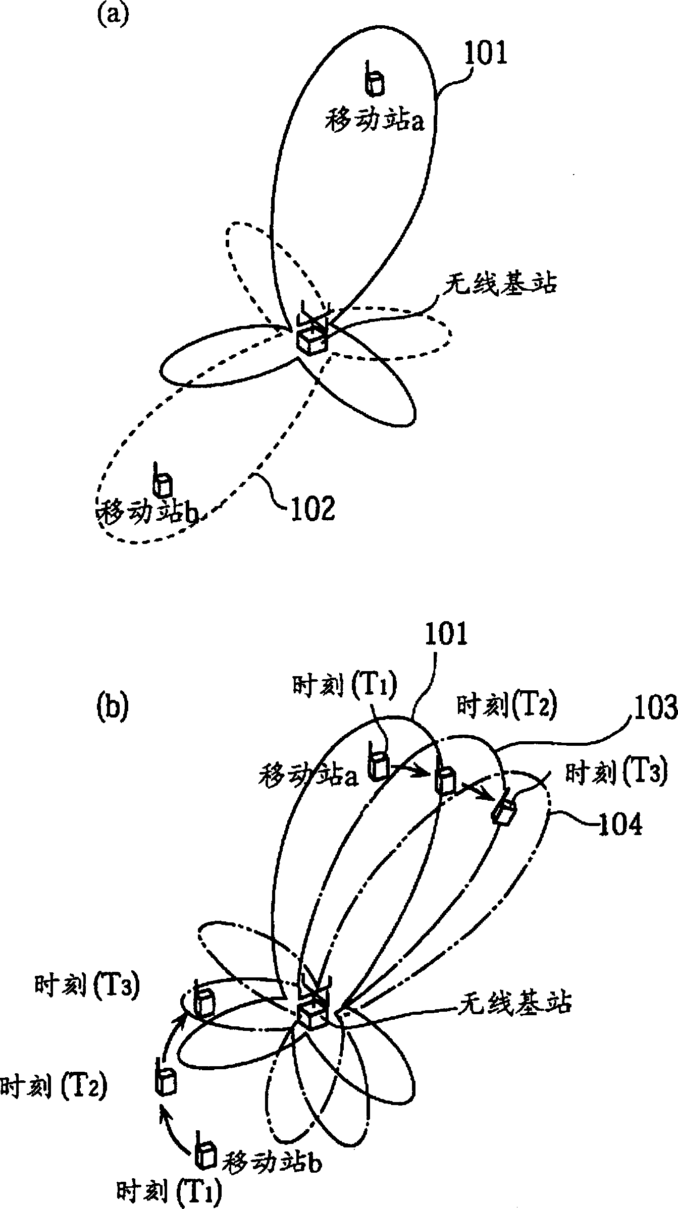
At time (T3), the mobile station b receives the direction of both the directional pattern (not shown) formed for the mobile station b and the directional pattern 103, and the signal received from the wireless base station is interfered by the directional pattern 103, preventing reception

Method used


Image

  • Radio base station
  • Radio base station
  • Radio base station

Examples


Embodiment Construction

[0041] A radio base station according to an embodiment of the present invention will be described below using the drawings.

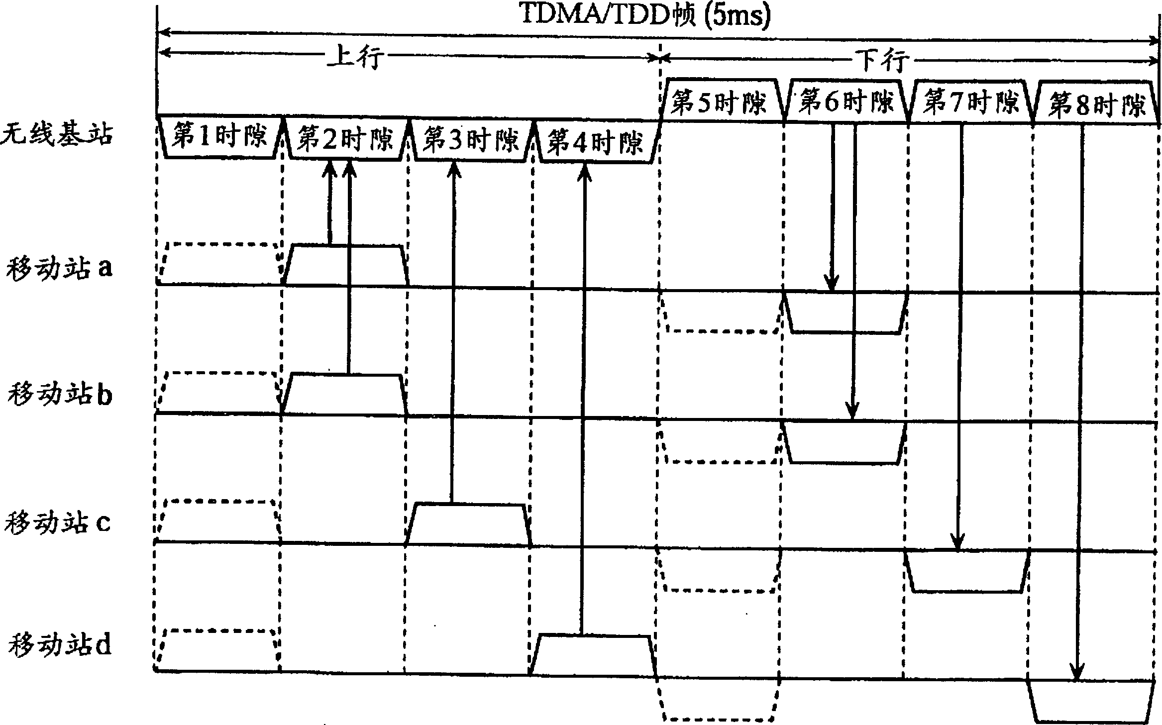
[0042] The wireless base station of the present embodiment has 4 antennas, performs spatial multiplexing communication with a maximum of 4 mobile stations through an adaptive array method, and uses the first time slot and the fifth time slot except for control signal transmission and reception through the TDMA / TDD method. The second and sixth slots, the third and seventh slots, and the fourth and eighth slots other than the slots perform time-division multiplex communication with a maximum of three mobile stations. The radio base station of the present embodiment performs multiplex communication with mobile stations a, b, c, and d using the TDMA / TDD frame structure shown in Figure 2 as an example of operation description. In this embodiment, the first time slot and the fifth time slot are determined as time slots for sending and receiving control signal...


PUM


Abstract

The wireless base station has a plurality of antennas, calculates a first weight vector for forming a directional pattern at the time of reception to form a directional pattern, and uses the first weight vector calculated at the time of transmission or at the time of reception before that to form the directional pattern at the time of reception. The pattern is the same as the directional pattern way to track the adaptive array way of the mobile station, and communicate with multiple mobile stations at the same time. In the case where the first weight vector for forming the current directional pattern of a mobile station cannot be calculated due to a reception error in the communication, the directional pattern to form zero pointing to other mobile stations is calculated based on the current response vectors of other mobile stations Using the second weight value vector, a mobile station using the second weight value vector forms a directional pattern and then communicates.

Description

technical field [0001] The present invention relates to a wireless base station that performs spatial multiplexing communication with multiple mobile stations by adjusting signals from multiple antennas to form a directional pattern, and particularly relates to improving the formation of a directional pattern. Background technique [0002] In recent years, in the field of mobile communications, the use of an adaptive array system for the purpose of efficient use of frequencies and improvement of communication quality has attracted attention. The so-called adaptive array method is a communication method that performs adaptive control of directional characteristics by independently controlling the amplitude and phase of each of a plurality of antennas. A wireless base station using this method controls a plurality of non-directional antennas to form a directional pattern with high reception sensitivity or transmission strength in the direction of arrival of a signal from a spe...

Claims


Application Information

Patent Timeline
IPC IPC(8): H04Q7/30H01Q21/00H01Q3/26H04B7/10H04B7/212H04B7/26H04J3/00H04J3/06H04L7/04
CPCH04J3/0605H04L7/042
Inventor 石田明
Owner KYOCERA CORP
Learn More