Ink line puller

A technology of puller and ink line, applied in workshop equipment, manufacturing tools, etc., can solve problems such as shortened life, ink specific gravity imbalance, ink line breakage, etc., achieve long contact time, short contact time, and prevent damage.

Inactive Publication Date: 2006-11-08
李学胜 +2
View PDF0 Cites 0 Cited by
  • Summary
  • Abstract
  • Description
  • Claims
  • Application Information

AI Technical Summary

Problems solved by technology

[0003] However, the above-mentioned conventional structure is prone to rainwater ingress and drying due to the exposed surface of the ink fountain, and problems such as ink staining on clothes or other tools are prone to occur during transportation.
In addition, because the ink line slips from the ink fountain box and the ink is transferred into the ink line, it is easy to damage the ink fountain, and the life of the ink line is shortened due to back and forth friction, and the ink line is prone to breakage.
Moreover, although the ink in the ink fountain can be transferred to the ink line smoothly when used on a horizontal plane, when used in a horizontal or oblique direction, the ink transferred to the ink line will be uneven due to the imbalance of the ink specific gravity in the ink fountain. defect

Method used


Image

  • Ink line puller
  • Ink line puller
  • Ink line puller

Examples


Embodiment Construction

[0012] Embodiments of the present invention will be described below with reference to the drawings.

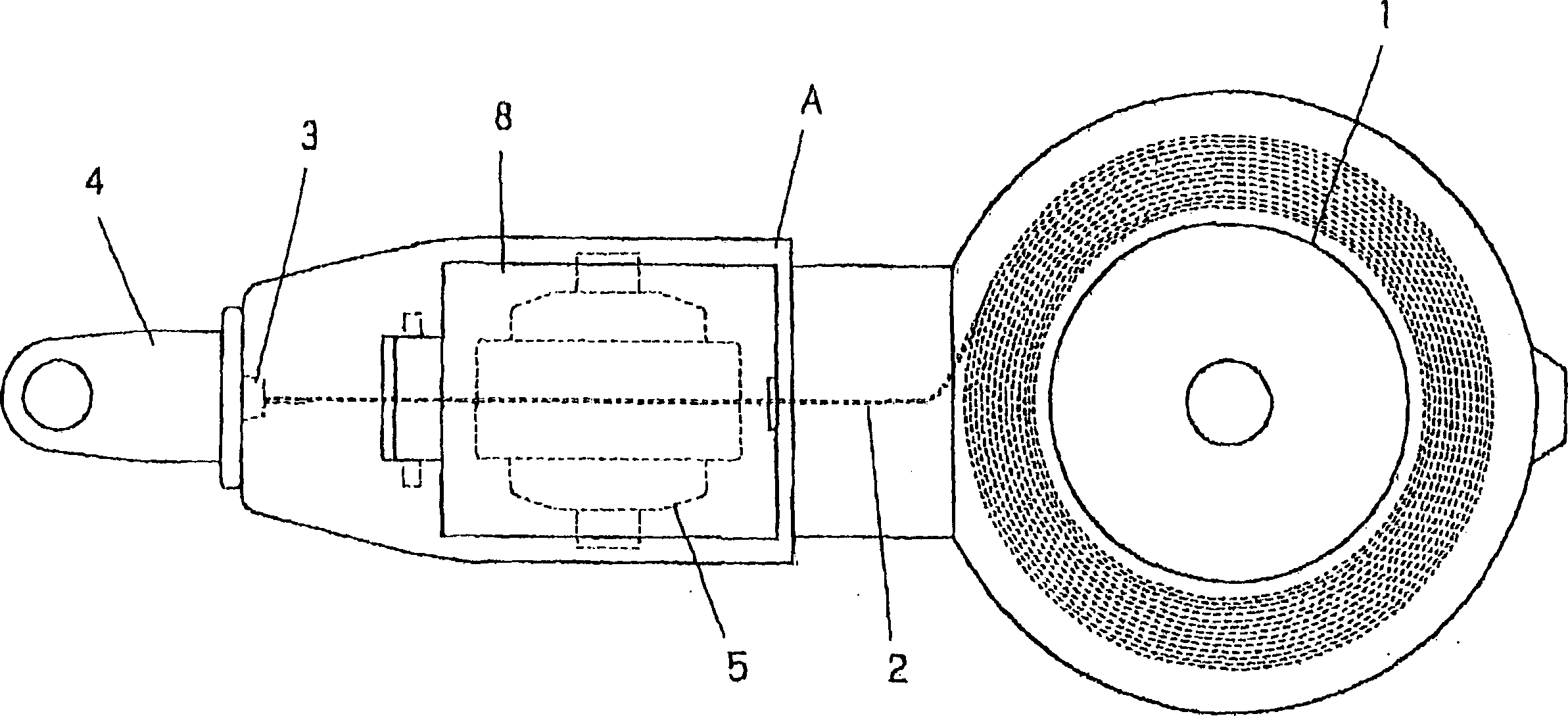
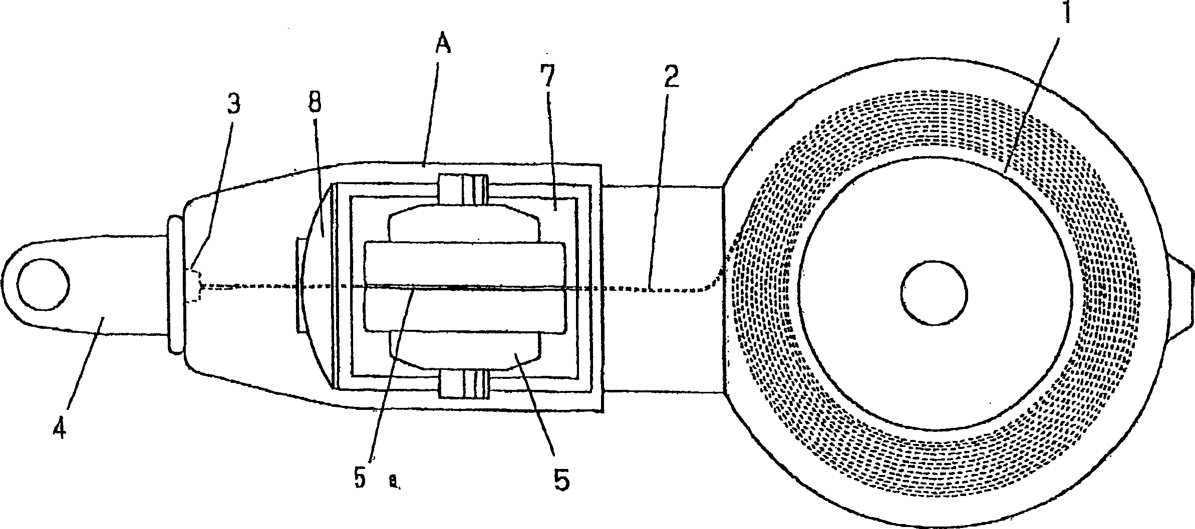
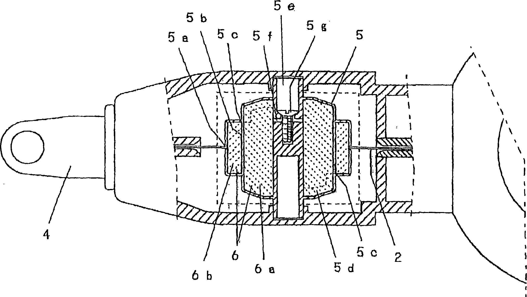
[0013] figure 1 is a plan view representing the overall shape, figure 2 is a plan view showing an open state, image 3 is a cross-sectional view of the rotary drum part, Figure 4 It is a longitudinal sectional view of the rotary drum part.

[0014] figure 1 , figure 2 The symbol A shown is a housing part, and the bobbin 1 is installed in the rear part. The spool 1 is a spring structure, which can automatically return to the normal winding state. In addition, the front end of the housing A is provided with a thread take-out port 3 for taking out the ink thread 2 wound on the spool, and a thread stopper 4 connected to the front end of the ink thread 2 is detachably installed at the thread take-out port 3 . The stop 4 has a needle 4a.

[0015] Between the bobbin 1 and the thread take-out port 3 is detachably disposed a rotary drum 5 for ink dipping that presses the ink...


PUM


Abstract

An ink thread puller, comprising: a bobbin (1) installed in a housing (A) and automatically returning to the state where the thread is always coiled; The thread take-out port (3) from which the ink thread is taken out is detachably installed on the thread take-out port (3) and connected to the end thread stopper (4) of the ink thread (2), and is detachably arranged on the spool ( 1) Between the thread outlet (3) and the rotary cylinder (5) that rotates in the forward and reverse directions according to the pulling out and pulling back of the ink thread (2) so that the ink thread (2) is pressed against its surrounding surface to carry ink The impregnated material (6) containing ink is accommodated inside the rotary drum (5), and a part of the outer peripheral wall of the rotary drum (5) is cut into a ring shape to form a cut groove (5a), so that the ink line (2) and The ink-containing impregnated material (6) contacts.

Description

technical field [0001] The invention relates to an ink line puller previously called "ink pot" used by carpenters to draw straight lines on pillars and boards. Background technique [0002] The ink thread puller formerly known as "ink pot" is formed in such a way that when the ink thread is pulled out from the spool, the ink thread contained in the ink fountain slides down and the ink is transferred to the thread, and the two ends of the ink thread are fixed. Use your finger to flick the ink line to trace a straight line on a target such as a pillar. [0003] However, the above-mentioned conventional structure is prone to rainwater ingress and drying due to the exposed top of the ink fountain, and problems such as ink staining on clothes or other tools are prone to occur during transportation. In addition, because the ink line slips from the ink fountain box and the ink is transferred into the ink line, it is easy to damage the ink fountain, and the life of the ink line is ...

Claims


Application Information

Patent Timeline
IPC IPC(8): B25H7/04
Inventor 李学胜丸岡好春高桥兴
Owner 李学胜
Why Eureka
Try Eureka