
Loop forming device for ring stitch sewing machine

A technology for sewing machines and stitches, which is applied to sewing machine components, sewing machine housings, sewing machine ferrule mechanisms, etc. It can solve the problems of inability to form loops and send out loops, etc., and achieve the effect of reliable formation

Inactive Publication Date: 2006-11-08
JUKI CORP
View PDF1 Cites 0 Cited by
  • Summary
  • Abstract
  • Description
  • Claims
  • Application Information

AI Technical Summary

Problems solved by technology

Pull out the place ahead of the thinned wire loop 32 in the feeding direction for this reason, as Figure 11 As shown, the wire loop is left on the side of the wire feeding ring tooth 28, so that the wire loop cannot be sent out to the cloth feeding direction, and there is a problem that the wire loop cannot be formed in essence.

Method used


Image

  • Loop forming device for ring stitch sewing machine
  • Loop forming device for ring stitch sewing machine
  • Loop forming device for ring stitch sewing machine

Examples


Embodiment Construction

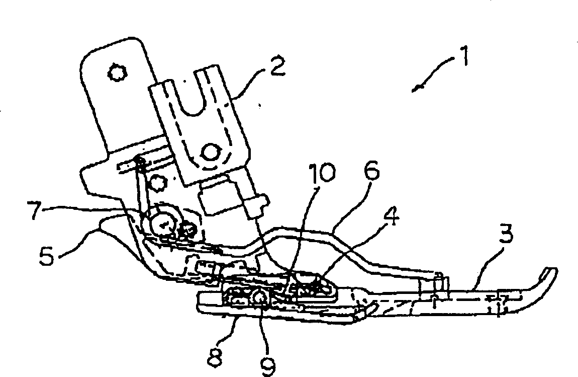
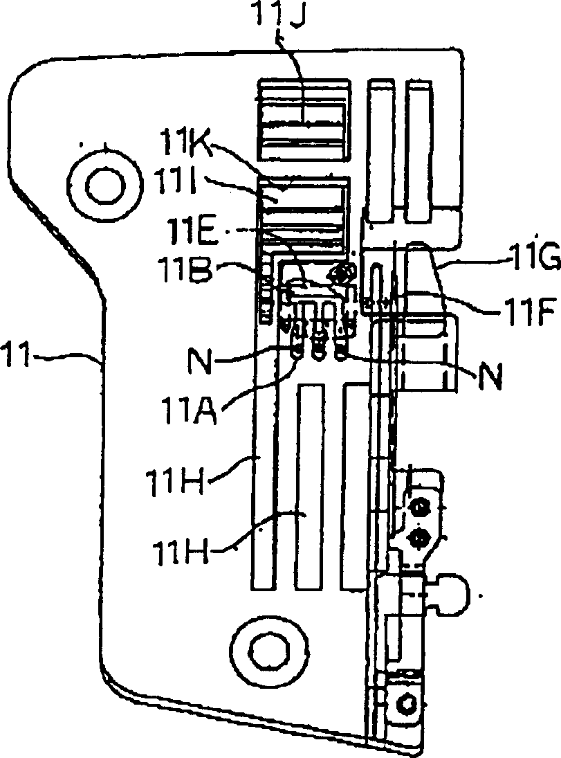
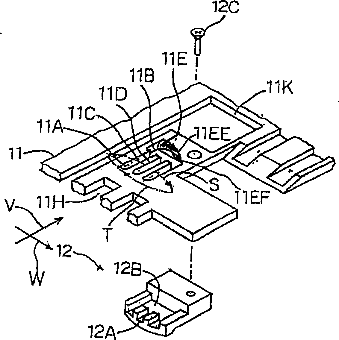
[0046] Below, refer to the embodiment of the present invention Figure 1 to Figure 6 Be explained.

[0047] The ring-type (chain-type) stitch sewing machine of this embodiment is a ring-type stitch sewing machine capable of overlock stitching and flat stitching, and will be described below based on this sewing machine.

[0048] figure 1 It is a side view of the cloth pressing device 1, and 2 is a support body, which is freely attachable and detachable at the lower end of the pressing rod not shown. 3 is a presser foot, and the shaft 4 in its horizontal direction can be loaded and unloaded with respect to the lower end of the support body 2 through a rod 5 . 6 is a spring, the base is supported by the shaft 7 of the support body 2, and the front end is crimped on the front of the presser foot 3, giving the presser foot 3 a rotational force clockwise around the shaft 4. Reference numeral 8 denotes a loop presser foot, which is supported by a horizontal shaft 9 rotatably rela...


PUM


Abstract

A thread loop forming device of a ring stitch sewing machine, which is composed of a plurality of machine needles with needle holes that pass through the needle plate and move up and down, with upper threads, and a needle that intersects with the cloth feeding direction under the needle plate The hook with the hook thread that moves back and forth in the direction, and the hook set on the needle plate that guides the thread loop formed by the upper thread and the hook thread to the rear of the cloth feeding direction through the coordinated action of the needle and the hook In the ring stitch sewing machine, the thread hole and the main conveying dog that is arranged behind the cloth feeding direction of the thread hole and sends the thread loop to the cloth feeding direction, the upper end edge of the thread hole behind the cloth feeding direction is Relative to the straight line perpendicular to the feeding direction, the side of the hook moving direction changes in the direction of the needle gradually approaching the plane shape, and the upper edge is set toward the hook moving direction, as it approaches A gradually shallower chamfered conductor surface is formed under the needle plate. This circular stitch sewing machine is capable of forming circular stitches reliably and smoothly.

Description

technical field [0001] The present invention relates to a loop forming device of a loop stitch sewing machine, in particular to a loop forming device of a loop stitch sewing machine which continuously forms loop stitches through a plurality of upper threads and hook threads. Background technique [0002] As a prior art of this type, a technique having a structure shown in Japanese Patent Application Laid-Open No. 2000-93671 is known. [0003] The composition of this known technology is passed Figure 8 , Figure 9 Be explained. [0004] Figure 8 It is a perspective view of a cloth pressing device and a needle plate, and 20 is a supporting body, which can be freely assembled and disassembled at the lower end of a pressing bar not shown. Reference numeral 21 denotes a presser foot, and is rotatably supported on the lower end of the support body 20 via its horizontal shaft 22 . Reference numeral 23 denotes a loop presser foot, which is supported by a horizontal axis 23A so ...

Claims


Application Information

Patent Timeline
IPC IPC(8): D05B1/08D05B61/00D05B73/12D05B1/10D05B27/02D05B29/08D05B57/02
CPCD05B1/10D05B29/08D05B57/02D05B73/12
Inventor 贞末数也
Owner JUKI CORP
Learn More