Bending device for tube

A bending device and tube technology, applied in the field of high-efficiency bending devices for long tubes, can solve the problems of increasing the processing capacity, the bending time cannot be shortened, etc., to achieve the effect of shortening the bending time, improving the accuracy and efficiency, and reducing the displacement

Inactive Publication Date: 2006-12-06
USUI CO LTD
View PDF5 Cites 0 Cited by
  • Summary
  • Abstract
  • Description
  • Claims
  • Application Information

AI Technical Summary

Problems solved by technology

This will inevitably increase the processing capacity, and lead to the disadvantage that the bending time cannot be shortened

Method used


Image

  • Bending device for tube
  • Bending device for tube
  • Bending device for tube

Examples


Embodiment Construction

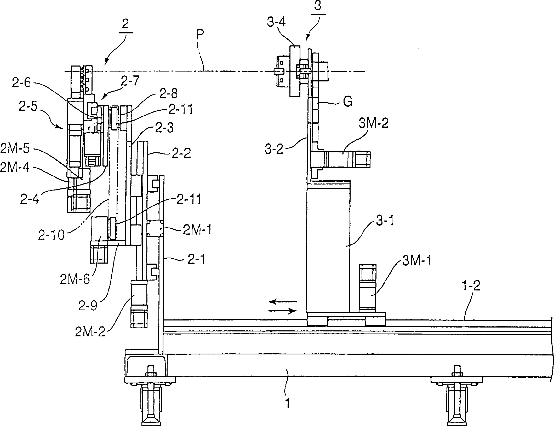
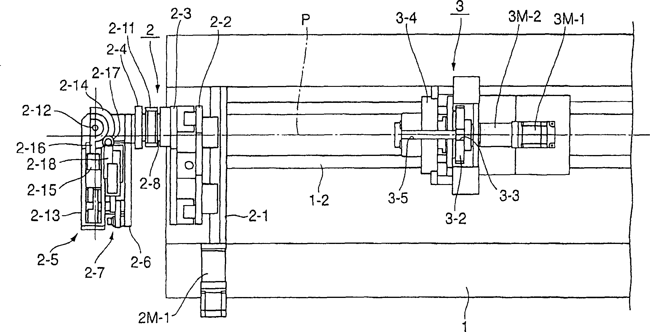
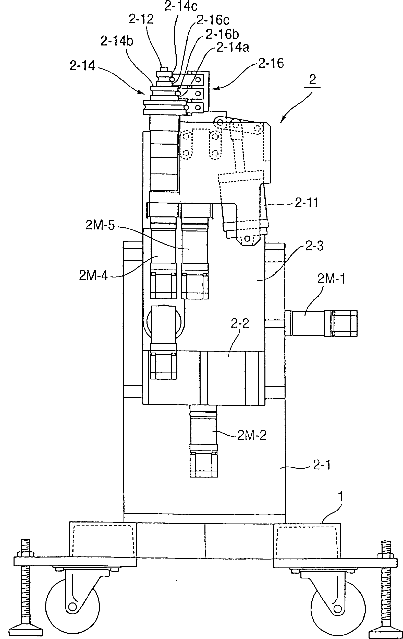
[0016] In the present invention, 1 denotes the base, 2 denotes the pipe bending assembly, 3 denotes the pipe twisting assembly and P denotes the processed pipe. Among them is a bending device composed of a pair of bending components with two functions of tension bending and compression bending, which will be described here by way of example.

[0017] That is to say, the pipe bending device according to the present invention includes a pipe bending assembly 2 and a pipe twisting assembly 3. Figures 1 to 6 The demonstration shows the pipe bending device with Figure 7 In both cases of the pipe bending device shown, the two components are mounted on the base 1 . exist Figures 1 to 6 In the illustrated pipe bending device, the pipe bending assembly 2 is fixedly mounted on the base 1, and the pipe twisting assembly 3 is placed on the base 1 so as to be movable along the axis center of the pipe P being processed. On the other hand, in Figure 7 In the shown pipe bending appara...


PUM


Abstract

A tube bending device having draw-bending and compression-bending functions and capable of bending in all processes in a unit of device is provided. The device performing bending by rotating the tube at a predetermined angle with the tube pressured against a circumferential surface of a bending die, the device including a movable type of tube bending unit movable in a longitudinal direction of a tube to be processed or a fixed type of tube bending unit and a tube twisting unit for rotating the tube freely at a predetermined angle with a center of the tube being an axis core is characterized in that the tube bending unit has one or both of draw-bending and compression-bending functions and is provided rotatably in a vertical plane about an axis parallel to the axis core of the tube so that the displacement amount in a tube twisting operation can be reduced.

Description

technical field [0001] The present invention relates to efficient bending devices for long tubes made of metal such as steel tubes, stainless steel tubes, copper tubes, titanium tubes and aluminum tubes. Background technique [0002] For example, the JP-8-B-29358 patent proposes a double bender (double bender) with a left component and a right component of a die assembly, and this double bender is exactly the above-mentioned bending device. In the double bending type bending die constituted by the right unit and the left unit, a bending unit mechanism has a separate structure and is arranged to be freely movable up and down with respect to the horizontal position of the long pipe, which is is supported and has a chuck mechanism portion interlocked with a feeding mechanism operating on a movable base in a reciprocating direction, while said movable base is arranged to be parallel in a right direction and a left direction mobile. [0003] In addition, as another known pipe b...

Claims


Application Information

Patent Timeline
Patent Type & Authority Patents(China)
IPC IPC(8): B21D7/08B21D7/025B21D7/024
CPCB21D7/024B21D7/08
Inventor 三枝茂
Owner USUI CO LTD
Why Eureka
Try Eureka