
Power transmission device, electric power steering device and manufacturing method therefor

The technology of a power transmission device and manufacturing method is applied in the direction of power steering mechanism, electric steering mechanism, transmission device, etc., which can solve the problems of poor driving feeling, increase, and increase the force required for the rotation of the steering shaft 3, and achieve improved Driving feeling, reduction of manufacturing cost, effect of reduction in number of parts

Inactive Publication Date: 2007-01-17
KYB CORP
View PDF6 Cites 0 Cited by
  • Summary
  • Abstract
  • Description
  • Claims
  • Application Information

AI Technical Summary

Problems solved by technology

[0005] However, in the conventional electric power steering device, since the rotating shaft 7B is connected to the output shaft 7A of the finished and assembled motor 5A through the connection cylinder 8A, two bearings are used in the motor 5A. The output shaft 7A is supported, and the rotary shaft 7B must be supported by two bearings 81A and 82A, and a total of four bearings are required
Therefore, the conventional electric power steering device has the problem of high cost due to the large number of parts, resulting in an increase in the size and weight of the device.
In addition, since the number of bearings is large, the force required to rotate the steering shaft 3 is increased, so there is also a problem of poor driving feeling.
In addition, in the conventional electric power steering device, since the output shaft 7A of the motor 5A and the rotating shaft 7B of the worm 61 are connected through the connecting cylinder 8A and the spline groove, spline processing is required, which increases the cost.
In addition, if there is looseness in the connection portion formed by the spline groove, noise is generated when the motor rotates, and there is also a problem that the responsiveness of the worm 61 to the rotation of the motor 5A deteriorates.

Method used


Image

  • Power transmission device, electric power steering device and manufacturing method therefor
  • Power transmission device, electric power steering device and manufacturing method therefor
  • Power transmission device, electric power steering device and manufacturing method therefor

Examples


Embodiment Construction

[0025] Hereinafter, an example of an electric power steering apparatus to which the present invention is applied and a method for manufacturing the same will be described with reference to the drawings.

[0026] [Electric Power Steering]

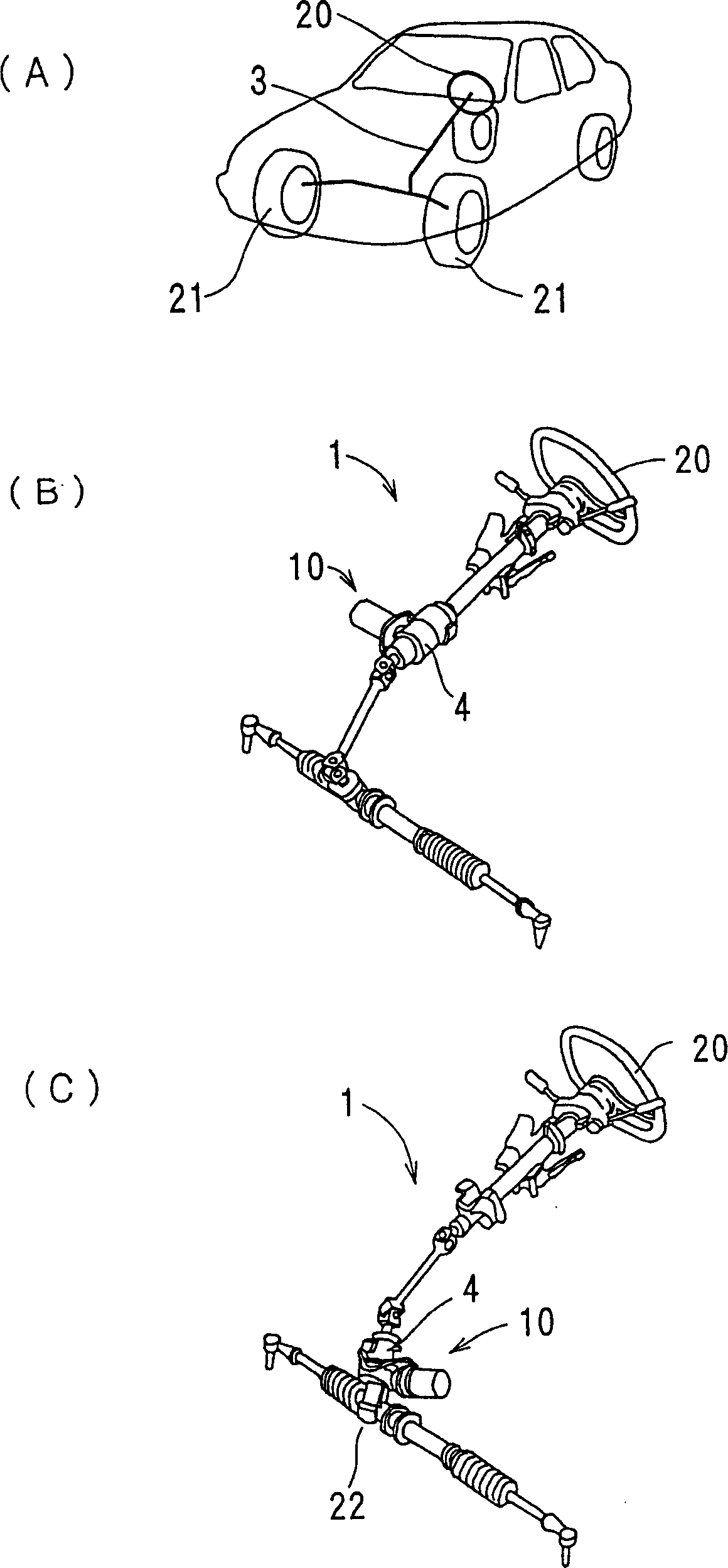
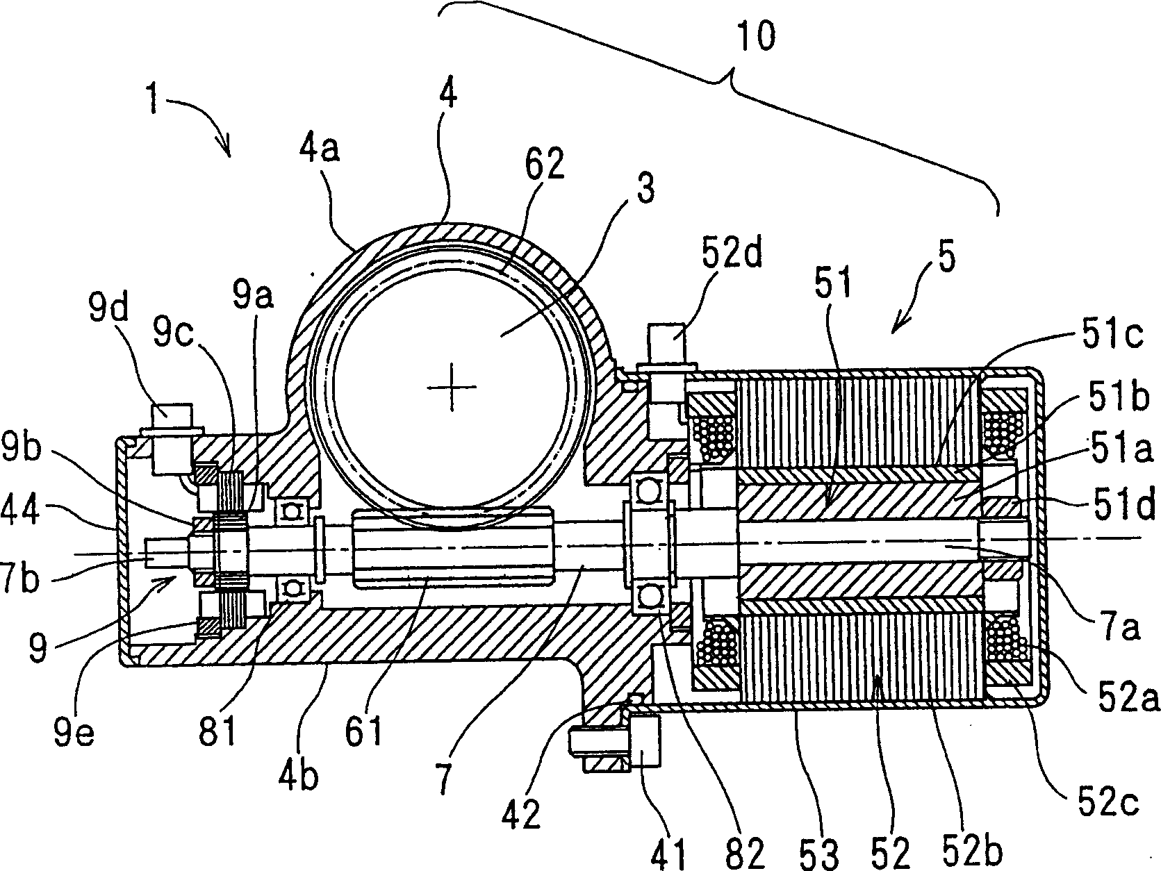
[0027] figure 1 (A), (B), and (C) are explanatory views each showing an electric power steering apparatus to which the present invention is applied. figure 2 It is a sectional view of the power transmission device used in the electric power steering device of the present invention.

[0028] Such as figure 1As shown in (A), in driving the automobile, the operation of the steering wheel 20 is transmitted to the wheels 21 through the steering shaft 3 . To assist this operation, in recent years such as figure 1 Like the electric power steering device 1 shown in (B), a power transmission device 10 having a reduction gear transmission and an auxiliary motor described later is often arranged in the bogie. Also, sometimes figure 1 Like th...


PUM


Abstract

A power transmission device (10) for an electric power steering device (1) intended to achieve reduced cost, small size, weight reduction, and responsiveness during power transmission and to prevent occurrence of noise, comprises a motor section (5) having a rotary shaft (7), a rotor (51) attached to the base end side (7a) of the rotary shaft (7), and a stator (52) disposed in opposed relationship to the rotor (51), a worm gear (61) attached to the front end side (7b) of the rotary shaft (7) as seen from the motor section (5), and a wormwheel gear (62) meshing with this gear (61). The rotary shaft (7) is rotatably supported on the front end side (7b) as seen from the worm gear (61) by a first bearing (81) and a second bearing (82) held in a housing (4). The second bearing (82) is held in the housing (4) between the worm gear (61) and the rotor (51) in such a manner as to cooperate with the first bearing (81) to hold the worm gear (61) therebetween.

Description

technical field [0001] The present invention relates to a power transmission device that transmits a rotational driving force of a motor through gears, an electric power steering device that provides steering assist driving for the power transmission device, and methods for manufacturing the same. Background technique [0002] When the steering wheel of a car is operated, the steering shaft rotates to change the rotational motion of its steering gear into a reciprocating motion to change the direction of the wheels. An electric power steering apparatus that assists such a steering operation with the rotational driving force of an electric motor is disclosed in, for example, Japanese Patent No. JP-A 2001-20623. [0003] In such an electric power steering device, a speed reduction device for transmitting the rotational driving force of the electric motor such as Figure 7 As shown, there are a motor 5A, a rotating shaft 7B connected to the output shaft 7A of the motor 5A throu...

Claims


Application Information

Patent Timeline
Patent Type & Authority Patents(China)
IPC IPC(8): F16H1/16B62D5/04H02K7/116B62D15/02H02K7/08H02K7/10H02K29/06
CPCY10T74/19828Y10T74/19684H02K7/081H02K7/1166B62D5/0403F16H1/16B62D5/0409B62D15/0235
Inventor 高桥昌志成濑信治
Owner KYB CORP
Learn More