Eureka AIR delivers breakthrough ideas for toughest innovation challenges, trusted by R&D personnel around the world.

Plastic stop valve

A cut-off valve, plastic technology, applied in the direction of lifting valves, valve devices, engine components, etc., can solve problems such as insufficient connection strength, affecting product quality and service life, and achieve the effect of solving insufficient connection strength

Inactive Publication Date: 2007-01-24
罗荣森
View PDF5 Cites 0 Cited by
  • Summary
  • Abstract
  • Description
  • Claims
  • Application Information

AI Technical Summary

Problems solved by technology

However, if the structure of this product is used for a plastic globe valve (that is, a globe valve whose valve body is made of plastic material), when the outer diameter of the plastic pipe connected to the plastic globe valve exceeds 63 mm, the inner cavity of the valve body The volume will be larger, and the pressure on the bonnet will also be greater. The above-mentioned metal insert embedded on the plastic valve body and used to fasten the bonnet needs to withstand a corresponding increase in strength. The distance between it and the plastic valve body There may be problems with insufficient connection strength at the joints between them, which will affect the quality and service life of the entire product

Method used


Image

  • Plastic stop valve
  • Plastic stop valve
  • Plastic stop valve

Examples


Embodiment 1

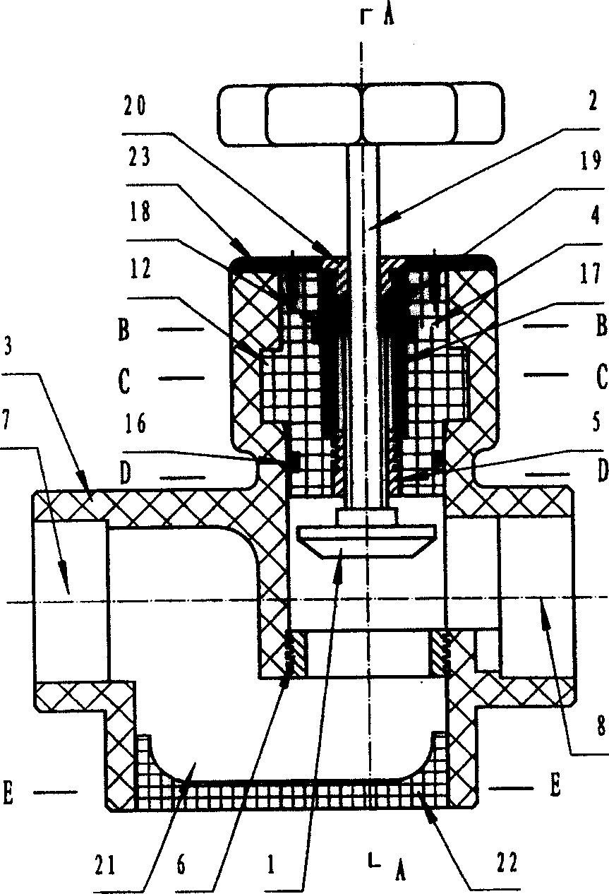
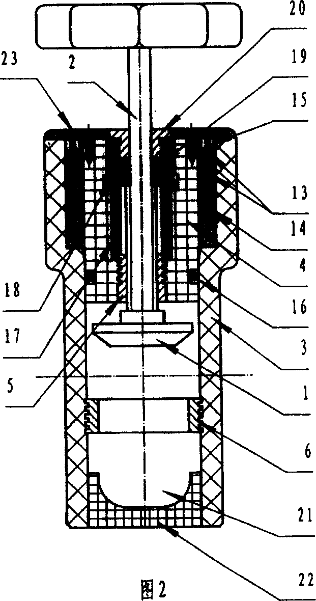
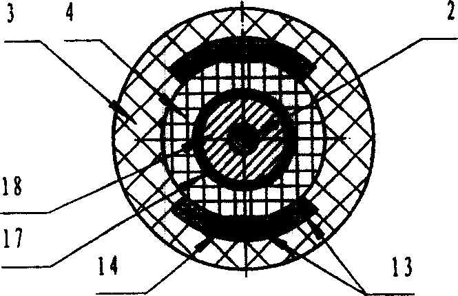
[0044] Embodiment 1: as Figure 1~1As shown in 3, the plastic globe valve in this embodiment has a valve cover, a valve disc 1, a valve stem 2 and a plastic valve body 3, and the plastic valve body 3 and the valve cover are connected through a valve cover connection structure. The bonnet is at least composed of a plastic bonnet base 4 and a valve stem nut insert 5 whose periphery is embedded and fixed on the plastic bonnet base. Screw holes are provided on the valve stem nut insert 5, and the valve stem 2 is sleeved on the In the screw hole, the external thread on the valve stem 2 cooperates with the internal thread of the screw hole to form a kinematic pair, and a valve seat 6 is arranged in the plastic valve body 3, and the valve seat 6 has a valve seat opening. The valve seat opening is opposite to the disc 1 located at the bottom of the valve stem, and the two ends of the plastic valve body 3 respectively have an inlet port 7 and an outlet port 8 communicating with the val...

Embodiment 2

[0053] Embodiment 2: as Figures 14-19 As shown, this embodiment is similar to Embodiment 1, the difference is that there are eight protrusions 12 on the side wall of the valve cover in this embodiment, and correspondingly, the above-mentioned grooves 11 leading to the recesses The number is also eight. At the same time, the valve seat 6 in this embodiment is no longer formed by a valve seat insert whose periphery is embedded in the plastic valve body, but is directly served by the plastic base material on the plastic valve body.

Embodiment 3

[0054] Embodiment 3: as Figure 20 As shown, the plastic shut-off valve in this embodiment is similar to that of Embodiment 2, the difference is that the inner walls of the hot-melt socket-type inlet 7 and the hot-melt socket-type outlet 8 in this embodiment are both A heating wire 24 is provided.


PUM


Abstract

The invention is a plastic stop valve, has a valve cover, valve petal, valve pole and plastic valve, the plastic valve body and the valve cover are connected together through connecting mechanism, the valve is at least made up of plastic cover base and peripheral valve pole screw embedding component embedded on the plastic valve base, a valve base is arranged in the plastic valve, the base has aperture, which is opposed to the valve petal on the bottom of the valve pole, the two ends of the plastic valve have inlet and outlet connected to the aperture, the top of the plastic valve matches with the valve cover connecting aperture matching with the valve cover, the concave part is arranged on the side of the side wall of the connecting aperture, the side wall of the connecting aperture arranges a groove connecting the inlet of the connecting aperture to the concave part, a convex part is arranged on the side wall of the valve cover, the convex part and the concave part match together and form a valve connection structure.

Description

technical field [0001] The invention relates to a plastic stop valve. Background technique [0002] Chinese utility model patent No. 02284141.5 discloses a shut-off valve, which includes a valve body, a valve seat (usually called a valve cover) and a valve stem, and a metal insert with an inner wire is embedded in the valve body, and the valve seat It is composed of seat core and seat body. In this product, the metal insert in the valve body is a bonnet connector, which is used for threaded connection with the valve seat (that is, the bonnet). However, if the structure of this product is used for a plastic globe valve (that is, a globe valve whose valve body is made of plastic material), when the outer diameter of the plastic pipe connected to the plastic globe valve exceeds 63 mm, the inner cavity of the valve body The volume will be larger, and the pressure on the bonnet will also be greater. The above-mentioned metal insert embedded on the plastic valve body and used to...

Claims


Application Information

Patent Timeline
Patent Type & Authority Patents(China)
IPC IPC(8): F16K1/02
Inventor 罗荣尧罗荣森
Owner 罗荣森
Why Eureka
Eureka Blog
Learn More