Electric incandescent lamp

An incandescent lamp, incandescent body technology, applied in the field of incandescent lamps, can solve the problems of high early failure rate, lamp leakage, short life, etc., and achieve the effect of avoiding strain and high dimensional accuracy

Inactive Publication Date: 2007-02-07
KONINKLIJKE PHILIPS ELECTRONICS NV
View PDF3 Cites 0 Cited by
  • Summary
  • Abstract
  • Description
  • Claims
  • Application Information

AI Technical Summary

Problems solved by technology

There are many restrictions on the positioning of the lamp's incandescent body relative to said lampshade, and

Method used


Image

  • Electric incandescent lamp
  • Electric incandescent lamp
  • Electric incandescent lamp

Examples


Embodiment Construction

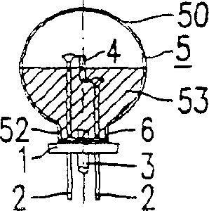
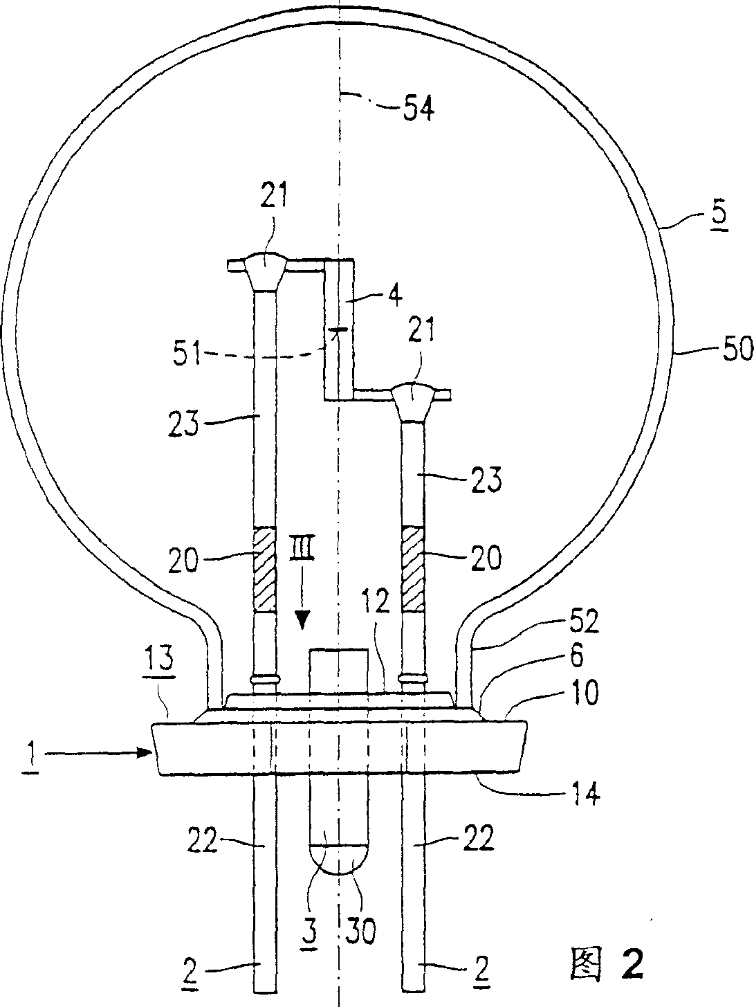
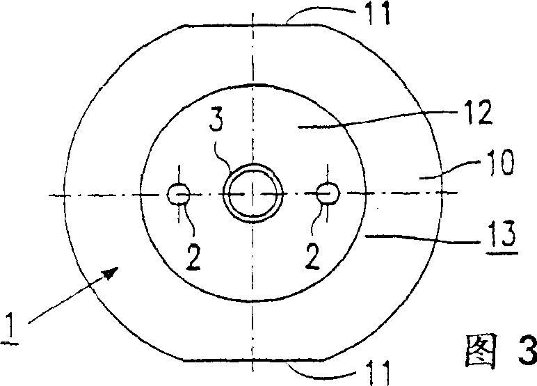
[0033] exist figure 1and 2, the incandescent lamp has a molded glass plate 1 connected in a gas-tight manner to a current conductor 2 and a metal tube 3 passing through said glass plate. The incandescent body 4 is connected to the current conductor 4 and occupies a predetermined position relative to the molded plate 1 . A glass bulb 5 is placed above the incandescent body 4 and is connected to the molded plate 1 in an airtight manner by means of enamel 6 . In the bulb 5 there is a filling gas at a pressure of at least 1 bar. The metal tube 3 has a gas-tight seal 30 outside the bulb 5 .

[0034] The glass pane 1 is a sintered body whose composition corresponds to that of the glass of the bulb 5 . In the accompanying drawings, the composition of the glass is roughly (by weight): SiO 2 , 67.59%; Al 2 o 3 , 3.56%; Li 2 O, 1.27%; Na 2 O, 7.38%; K 2 O, 4.88%; MgO, 1.24%; CaO, 1.89%; SrO, 3.04%; BaO, 8.81%; CeO 2 , 0.12%; SO 3 , 0.17%; the rest 0.05%. Both the glass of th...


PUM


Abstract

The electric incandescent lamp has a sintered glass plate (1) through which current conductors (2) and a metal tube (3) extend. An incandescent body (4) is connected to said current conductors (2) aligned with respect to the plate (1). A glass bulb (5) is present over the incandescent body (4), gastight secured to the plate (1) by means of enamel (6). A water getter (20) and a heavy gas at an elevated pressure are present inside the glass bulb (5). The lamp may consume a relatively high power and may be relatively small, but nevertheless has a relatively long life.

Description

technical field [0001] The invention relates to an incandescent lamp. Background technique [0002] Such an incandescent lamp is known from FR-B-913579. [0003] This known lamp has a molded or cast glass plate with rounded edges and a positioning post on the glass plate. The lamp is designed so that the front bulb passes through the opening in the reflector and the edge of the lamp panel is pressed against the border of the opening to create a pressurized environment. Lighted reflectors are used as headlights in cars for search beams and driving beams. [0004] A disadvantage of this known electric lamp is that the glass panes produced have large dimensional tolerances. This means that the position of the incandescent body thus determined also has a large error. [0005] In other applications of incandescent lamps, such as in the rear of motor vehicles such as electric vehicles, it is desirable to have available incandescent lamps that can be moved rearwardly (i.e., wit...

Claims


Application Information

Patent Timeline
IPC IPC(8): H01K1/22
CPCH01K1/22
Inventor U·布吕格曼W·L·科尔曼J·M·J·格伯尔斯A·J·M·范赫斯
Owner KONINKLIJKE PHILIPS ELECTRONICS NV
Why Eureka
Try Eureka