Nozzle of vortex tube

A technology of vortex tubes and nozzles, which is applied in the refrigeration field of Ming Dynasty, can solve the problems of large energy loss, small unit cooling capacity, and low energy separation efficiency, so as to increase the cold flow rate, increase the unit cooling capacity, increase the unit cooling capacity and The effect of cooling coefficient

Inactive Publication Date: 2007-03-14
BEIJING UNIV OF TECH
View PDF1 Cites 1 Cited by
  • Summary
  • Abstract
  • Description
  • Claims
  • Application Information

AI Technical Summary

Problems solved by technology

[0004] In order to solve the problems of large energy loss, small unit cooling capacity and low energy separation efficiency of the existing vortex tube, the present invention proposes a vortex tube nozzle, which can improve the cooling temperature effect of the vortex tube on the one hand; on the other hand, It can increase the cold flow rate when the vortex tube reaches the maximum cooling temperature effect, thereby increasing the unit cooling capacity and refrigeration coefficient of the vortex tube

Method used


Image

  • Nozzle of vortex tube
  • Nozzle of vortex tube
  • Nozzle of vortex tube

Examples


Embodiment 1

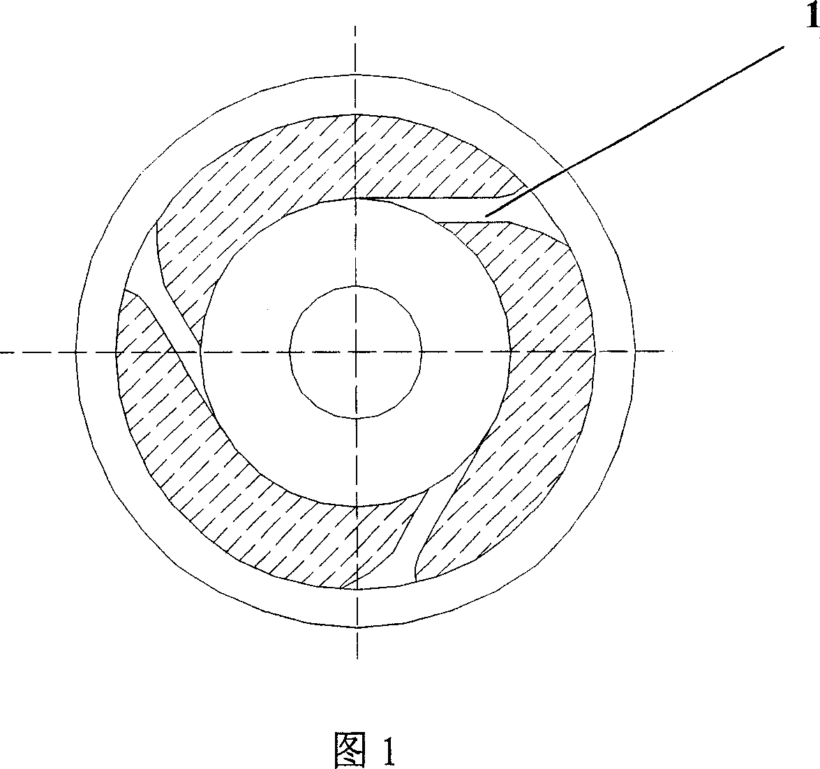
[0046] In this implementation, compared with the existing ordinary nozzles, only the profile of the nozzle flow channel 1 is changed. As shown in FIG. 8 and FIG. 9, the nozzle 6 of the present invention and the cold end tube 4 of the vortex tube are integrated as a whole. Replace the parts and install the corresponding position of the vortex tube. The Mach number at the exit of the nozzle flow channel is 0.57, and the Mach number at the entrance is 0.19.

[0047] Ordinary rectangular nozzle size: cold air hole diameter 5.6mm, swirl chamber diameter 13mm, nozzle outer circumference is straight

[0048] Diameter 20mm, nozzle runner groove width L=2mm, nozzle runner groove depth H=1mm,

[0049] The nozzle material is plexiglass.

[0050] Archimedes spiral nozzle: same size and material as ordinary rectangular nozzle

[0051] The size of the nozzle of the present invention: the groove width at the entrance of the nozzle flow channel L e =3mm, the groo...

Embodiment 2

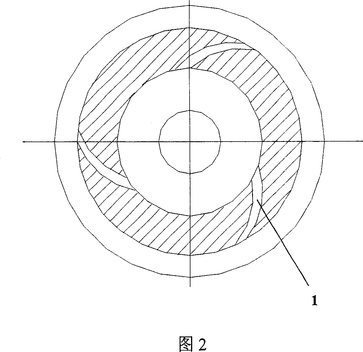
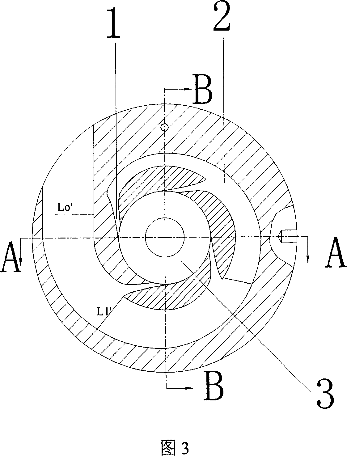
[0055] At the same time, change the nozzle flow channel 1 profile and the nozzle inlet flow channel shape. Refer to Figures 3, 4, and 5 for details, the number of nozzle runners is 3, and the slot width at the inlet of runner 2 before air intake is L 0 ′ Is 7.2mm, and the nozzle 6 and the cold end pipe 4 are connected by ribs. The assembly of the nozzle and other parts of the vortex tube is shown in FIG. 10. Other dimensions of the nozzle: same as the first embodiment.

[0056] effect:

[0057] The inlet pressure is 0.4MPa (absolute pressure), the inlet temperature is 24°C, the hot end pipe is 140mm long, and the number of nozzles is 3. The nozzle vortex tube of the present invention has a cold flow rate of 56.2%, reaching the lowest cold end temperature of -5.5°C; and under the same test conditions, using an ordinary rectangular nozzle, the vortex tube reaches the lowest cold end temperature when the cold flow rate is 48.5% Temperature -0.7°C. When the cold flow rate of the nozzl...


PUM


Abstract

The invention is the vortex tube nozzle and belongs to the refrigeration field. The characteristics are: the flow channel (1) of the nozzle adopts the geometrical symmetry, which is that the central axis line of the flow channel is designed by the equal Mach grads and makes the air flow increase along the axis line to reduce the lost of the air flow; the air intake front channel (2) of the nozzle adopts the design of the same plane with the nozzle channel (1) and the equal air speed, which is to ensure the speed of the normal face of the central line of the air channel consistent to the intake of the vortex tube. The invention improves the refrigeration temperature effect of the vortex tube and increases the chill flow ratio of the maximum refrigeration to improve the unit refrigeration volume and the refrigeration coefficient.

Description

Technical field [0001] The invention clearly belongs to the field of refrigeration, and specifically relates to a vortex tube nozzle. Background technique [0002] The vortex tube is a separation device that converts pressure energy into velocity energy, and then divides the intake air flow into two airflows with different total temperatures through vortex transformation. It consists of a tube with two ends open, nozzles, and vortex. The chamber, the hot end pipe and the cold end outlet respectively located on both sides of the vortex chamber, the hot end valve at the end of the hot end pipe, the hot end outlet, and the cold end orifice plate located between the cold end outlet and the vortex chamber. The nozzle is the key component in the vortex tube that converts pressure energy into velocity energy. The higher the nozzle outlet velocity, the lower the thermodynamic temperature at the outlet, and the better the refrigeration performance of the vortex tube, so the nozzle design ...

Claims


Application Information

Patent Timeline
Patent Type & Authority Patents(China)
IPC IPC(8): F25B9/04
CPCF25B9/04
Inventor 马重芳吴玉庭何曙葛满初
Owner BEIJING UNIV OF TECH
Why Eureka
Try Eureka