Exhaust-recirculation controlling device
A technology for exhaust gas recirculation and control devices, which is applied in the direction of exhaust gas recirculation, exhaust devices, valve devices, etc., and can solve problems such as burnout, motor failure, and increased motor drive current for driving the shaft
- Summary
- Abstract
- Description
- Claims
- Application Information
AI Technical Summary
Problems solved by technology
Method used
Image
Examples
no. 1 example
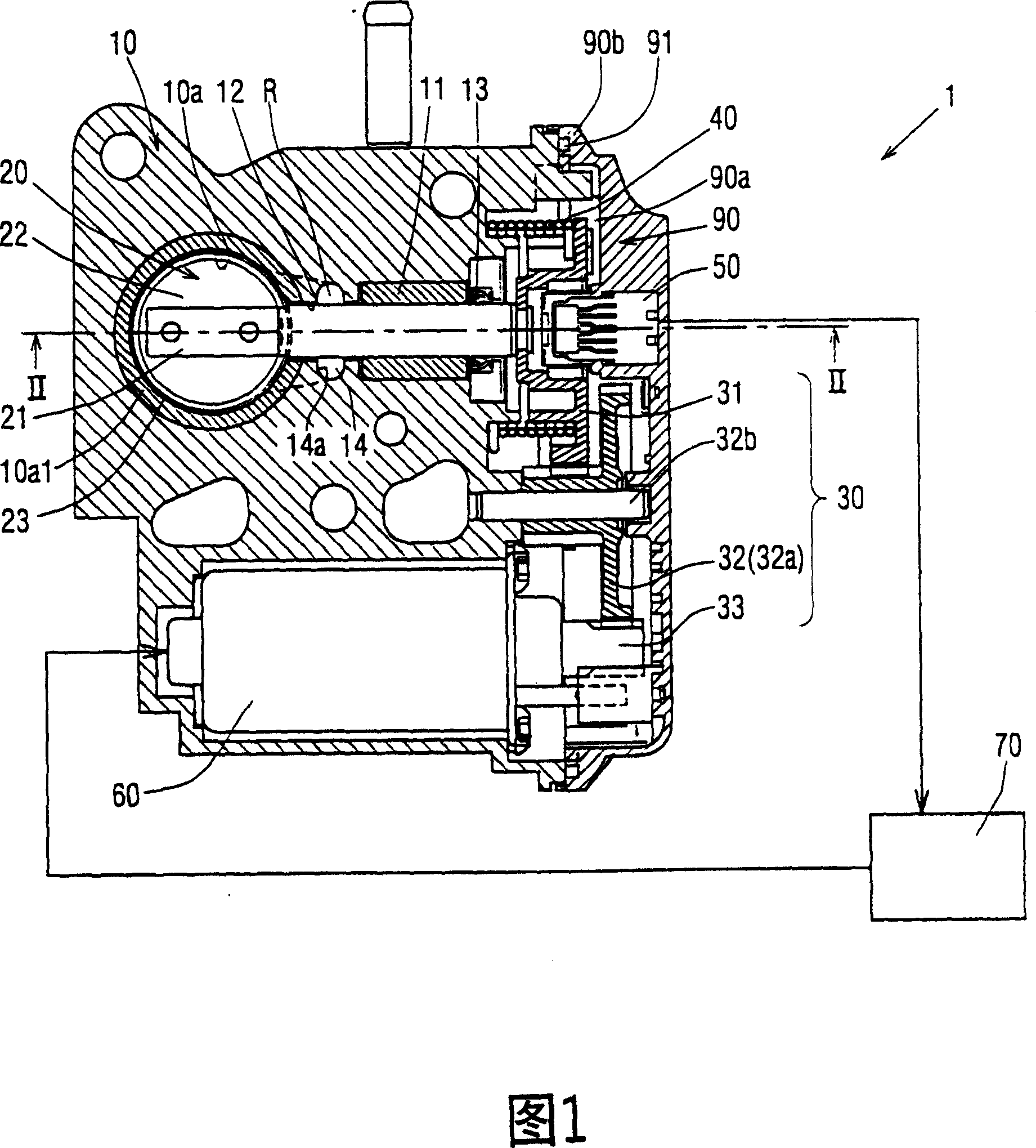
[0024] Referring to Fig. 1, the EGR control device according to the first embodiment of the present invention will be described.
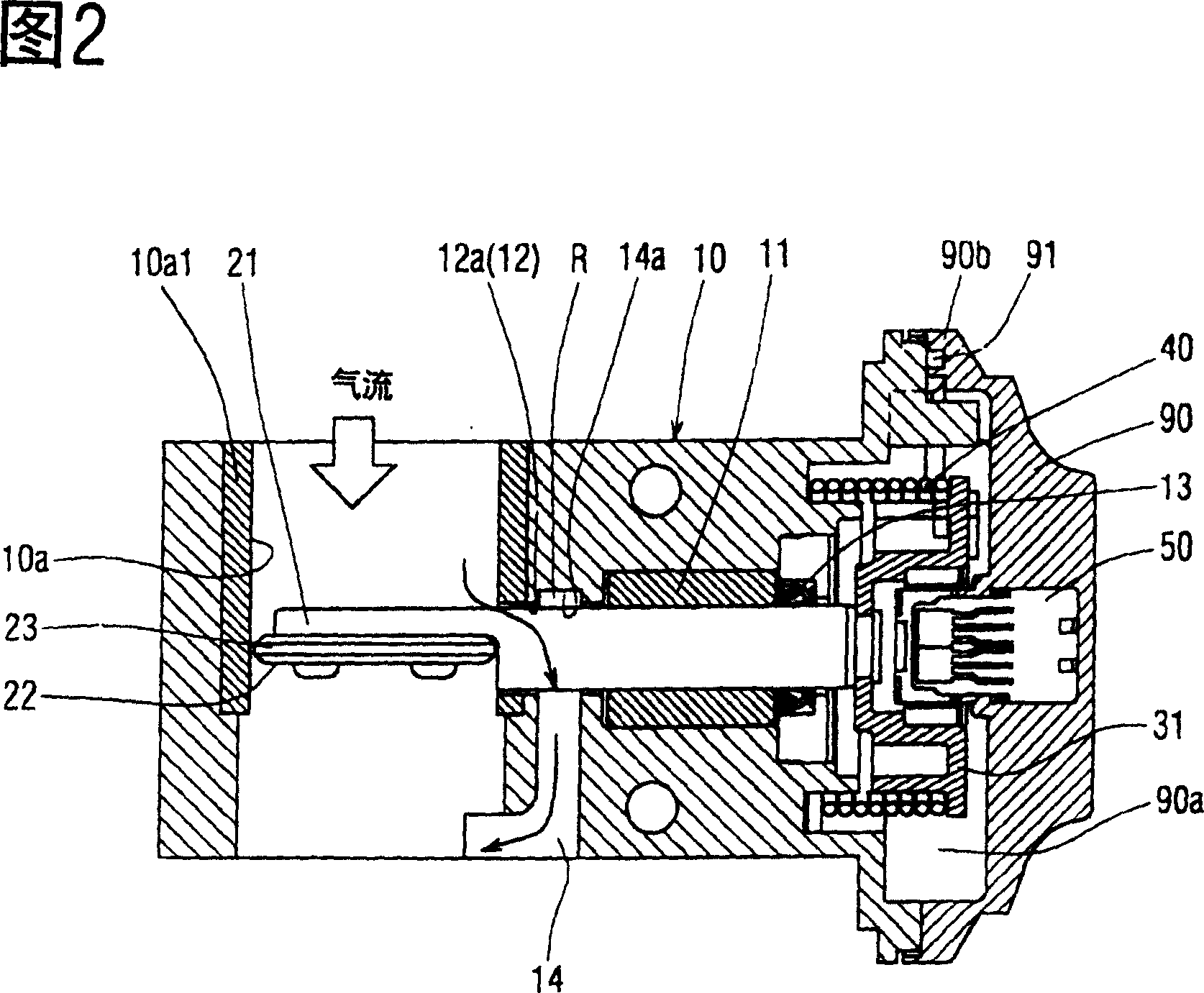
[0025] As shown in Fig. 1, an exhaust gas recirculation control device 1 includes a valve casing 10 with a gas passage 10a formed therein, a butterfly valve 20, a deceleration device 30, a return spring 40 as a pushing element, a valve shaft opening A degree sensor 50, a driving motor 60, and a control device 70. The exhaust gas recirculation control device 1 utilizes the opening and closing movement of the butterfly valve 20 to recirculate the exhaust gas discharged from the combustion chamber of the internal combustion engine into the intake pipe through the gas passage 10a. The driving motor 60 controls the rotational driving of the butterfly valve 20 .
[0026] The butterfly valve 20 is placed in a gas passage 10 a formed in the valve housing 10 . The butterfly valve 20 adjusts the flow rate of the exhaust gas flowing downstream of the intake...
no. 2 example
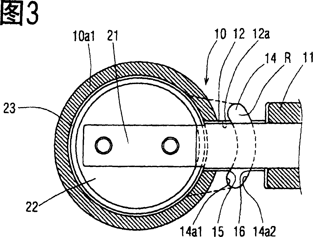
[0047] The EGR control device of the second embodiment will be described below with reference to FIG. 3 .
[0048] In the second embodiment, an intersection 15 is formed at the junction between the first inner surface 14a1 of the sediment return tank 14a on one side of the gas passage 10a and the inner surface 12a of the cavity 12, as shown in FIG. 3 . At the intersection portion 15, the first inner surface 14a1 of the sediment return tank 14a and the inner surface 12a of the containing hole 12 form an acute angle.
[0049] Therefore, even if particulate matter or the like enters the gap between the valve shaft 21 and the receiving hole 12 and settles on the first inner surface 14a1 of the sediment return groove 14a and the second inner surface 14a2 of the bearing end, the fastening on the valve shaft 21 The rotational force required for deposits on the inner surface 14a1 is also reduced. Therefore, by driving and controlling the drive motor 60 to rotate the valve shaft 21 ,...
no. 3 example
[0051] In the EGR control system according to the third embodiment of the present invention, an intersection is formed at the junction between the second inner surface 14a2 of the sediment return tank 14a on the side of the bearing 11 and the inner surface 12a of the receiving hole 12 16, as shown in Figure 4. At the intersection portion 16, the second inner surface 14a2 of the sediment return groove 14a at the end of the bearing 11 and the inner surface 12a of the containing hole 12 form an acute angle.
PUM
 Abstract
Description
Claims
Application Information
 - R&D
- Intellectual Property
- Life Sciences
- Materials
- Tech Scout
- Unparalleled Data Quality
- Higher Quality Content
- 60% Fewer Hallucinations
Browse by: Latest US Patents, China's latest patents, Technical Efficacy Thesaurus, Application Domain, Technology Topic, Popular Technical Reports.
© 2025 PatSnap. All rights reserved.Legal|Privacy policy|Modern Slavery Act Transparency Statement|Sitemap|About US| Contact US: help@patsnap.com


