

Energy absorber system for attachment to vehicle
An energy absorption and energy absorber technology, applied in vehicle components, vehicle safety arrangements, bumpers, etc., can solve problems such as vehicle damage, and achieve the effects of increased safety, easy recovery, and consistent impact resistance.
- Summary
- Abstract
- Description
- Claims
- Application Information
AI Technical Summary
Problems solved by technology
Method used
Image

Examples
Embodiment Construction
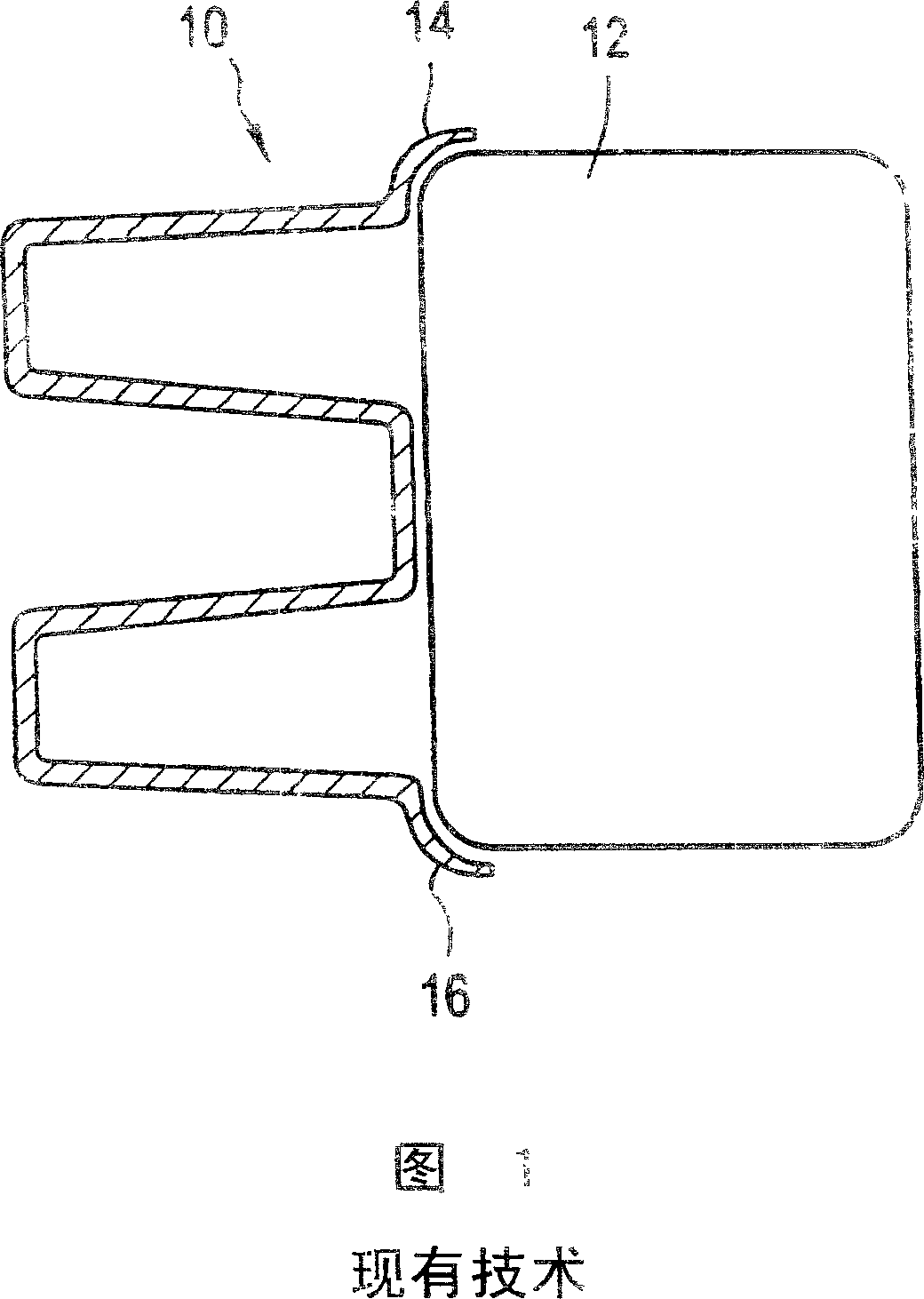
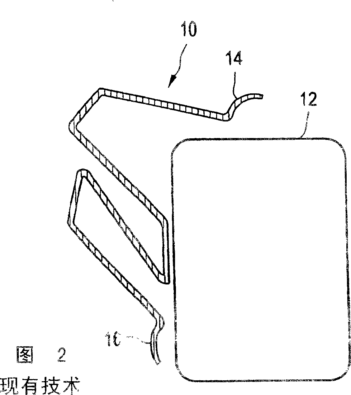
[0023] Referring to Figures 1 and 2, a prior art energy absorber 10 for use in association with a reinforcing beam 12 is shown in cross-section. As shown, the energy absorber includes upper and lower flanges 14 and 16, respectively, which when mounted overlap a portion of the beam. As shown more clearly with reference to FIG. 2 , prior art energy absorbers tend to twist, as opposed to absorbing and dissipating the impact energy resulting from a collision. Of course, this is undesirable and contrary to the energy absorber of the present invention.
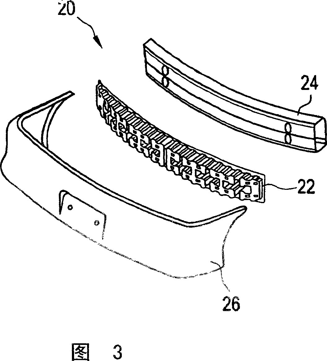
[0024] As shown in FIG. 3, the present invention relates to an energy absorbing system 20 comprising an energy absorber 22 positioned between a reinforcement beam 24 and an outer wall panel 26 which, when assembled, forms the bumper. Those of ordinary skill in the art will understand that the reinforcement beams are connected to longitudinally extending frame bars (not shown) and are made of high strength materials such as steel, ...
PUM
 Abstract
Description
Claims
Application Information