
Servo control valve

A technology for controlling valves and valve sleeves, applied in the field of servo control valves, which can solve problems such as the increase of price actuators, and achieve the effect of continuous and reliable work

Inactive Publication Date: 2007-04-18
HIH DEV
View PDF8 Cites 0 Cited by
  • Summary
  • Abstract
  • Description
  • Claims
  • Application Information

AI Technical Summary

Problems solved by technology

Therefore, as the size of the valve increases, the price of said valve increases greatly due to the relatively expensive actuator

Method used


Image

  • Servo control valve
  • Servo control valve
  • Servo control valve

Examples


Embodiment Construction

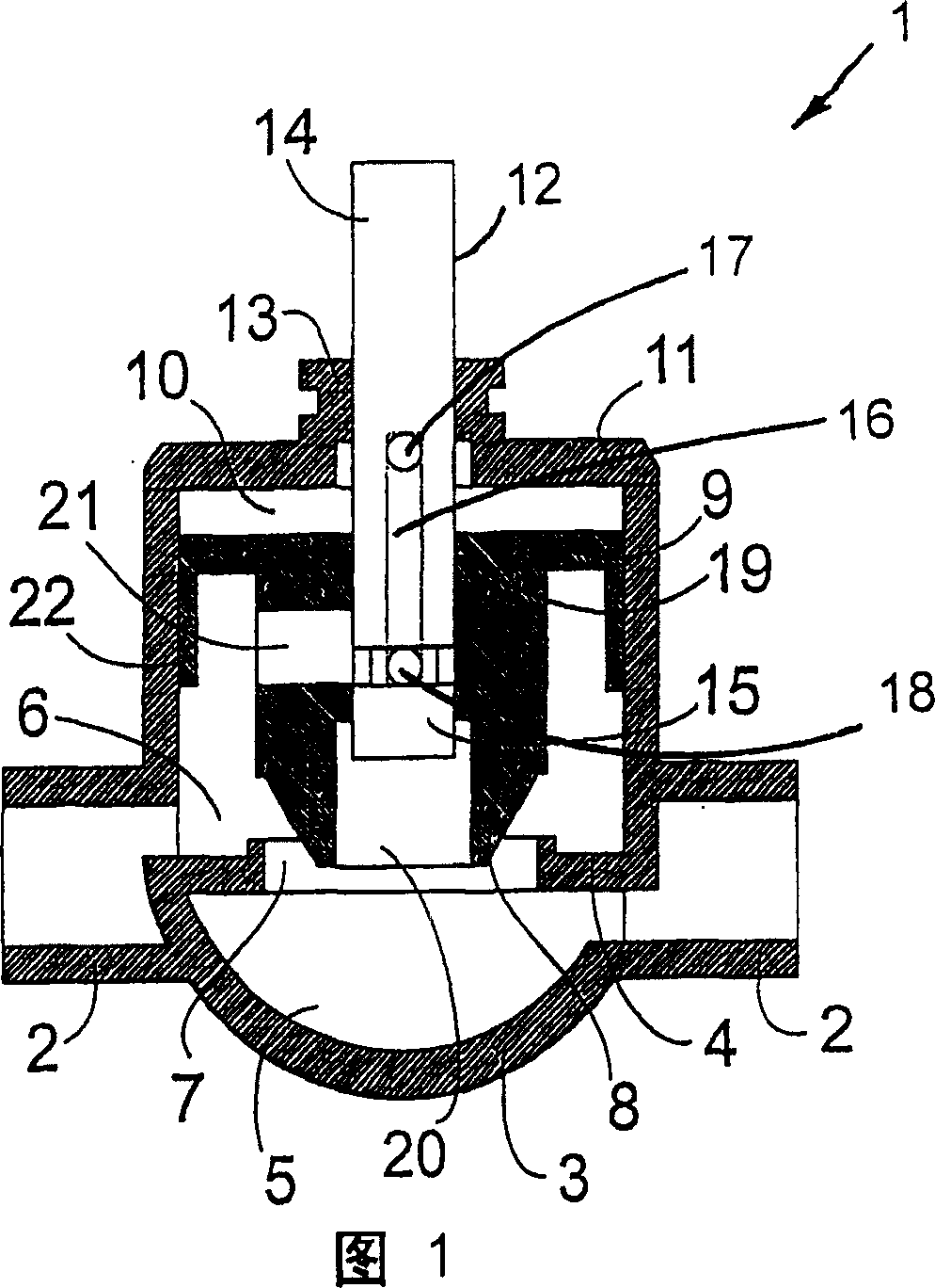
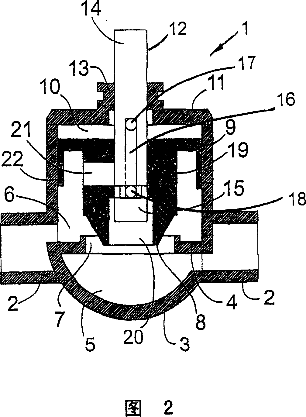
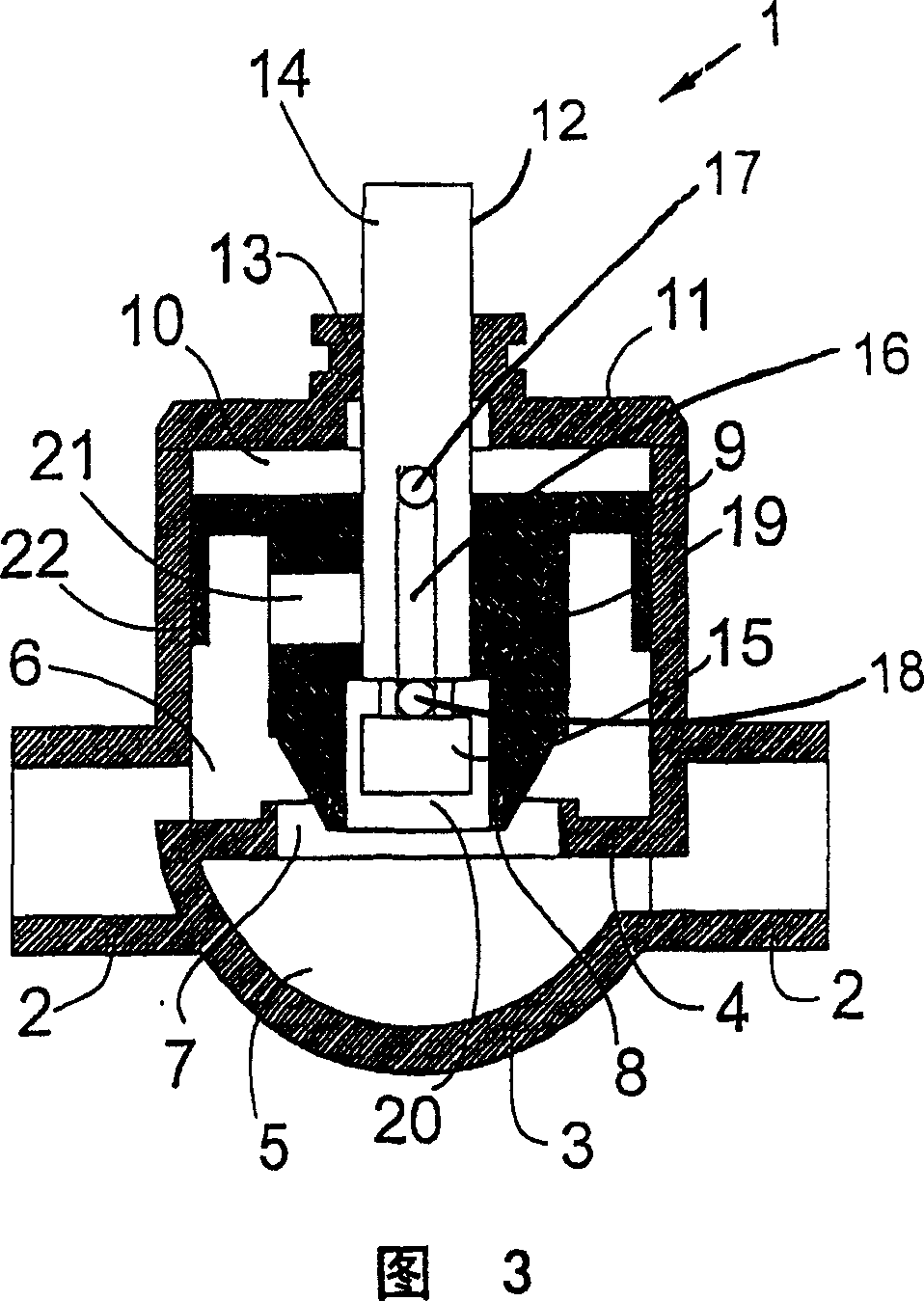
[0039] It is assumed below that the control valve is connected to the supply pipe of the radiator (not shown in the figure). As shown in the figure, the radiator is connected to the left section of the pipe. As shown by the arrow, the water flows through the valve from right to left.

[0040] In FIGS. 1-5, the control valve is generally indicated by the reference number 1, and the supply pipe, which is only partially shown, is generally indicated by the reference number 2.

[0041] The valve has a valve sleeve 3 divided into a first part 5 and a second part 6 by a partition 4. The two parts 5, 6 are respectively located upstream and downstream of the valve connected to the pipeline 2.

[0042] In addition, the partition 4 has a fluid through hole 7 through which water in the radiator can flow.

[0043] According to conditions such as room temperature, by keeping a sufficient distance from the fluid through hole, the valve cone 8 on the movable plunger 9 functions to close the flui...


PUM


Abstract

A control valve (1) for controlling liquid flow in a pipeline (2). The valve (1) comprise, a valve housing (3), which by a passage (7) is divided in a first and second section (5;6). The valve comprises a pressure chamber (10), which is in open connection with the valve house (3) second section (6), and a piston (9), which is movably placed in the pressure chamber (10). One in the valve house (3) movably or rotatably mounted positioning rod (12;24) wherein there are provided a connection conduit (16,17;18;25) which at one end communicates with the pressure chamber (10) and in a first of the positioning rod (12;24) positions in relation to the piston (9) further communicates with this at least one first conduit (20), in a second position with this at least one second conduit (21) and in a third position with none of these conduits (20;21). The regulating valve has prolonged reliability and allows easy and safe regulation by means of a small application of force, which can be supplied by a corresponding small actuator.

Description

Technical field [0001] The invention relates to a servo control valve for controlling fluid flow in a pipeline, comprising a valve sleeve divided by a fluid through hole defining an axis into a first part and a second part connected to a pipeline and respectively located upstream and downstream of the valve , A pressure chamber that is preferably designed to be coaxial with the fluid through hole and communicated with the second part of the valve sleeve, and a pressure chamber that is movably placed in the pressure chamber and has a fluid through hole for controlling the flow area of ​​the valve The end of the plunger. Background technique [0002] This type of valve is mainly used to control the fluid flow rate in a pipeline that is part of, for example, a cooling or heating system. [0003] In the supply pipe leading to the radiator of the central heating system, a valve is usually connected to control the flow rate of the water flow and thereby control the heat discharge of th...

Claims


Application Information

Patent Timeline
Patent Type & Authority Patents(China)
IPC IPC(8): F16K31/122F16K1/00F16K39/02
CPCF16K39/022F16K39/024
Inventor L·哈尔格伦
Owner HIH DEV
Learn More