Supercharge Your Innovation With Domain-Expert AI Agents!

Apparatus and method for recovering and recirculating optical-fiber coolant gas

A coolant, recycling technology, used in lighting and heating equipment, household refrigeration units, glass manufacturing equipment, etc., to solve problems such as increased concentrations of pollutants

Inactive Publication Date: 2007-05-30
BOC GRP INC
View PDF6 Cites 0 Cited by
  • Summary
  • Abstract
  • Description
  • Claims
  • Application Information

AI Technical Summary

Problems solved by technology

As an attempt is made to recirculate more of the recovered coolant gas, the resulting concentration of pollutants in the recovered coolant gas will increase

Method used


Image

  • Apparatus and method for recovering and recirculating optical-fiber coolant gas
  • Apparatus and method for recovering and recirculating optical-fiber coolant gas
  • Apparatus and method for recovering and recirculating optical-fiber coolant gas

Examples


Embodiment Construction

[0020] Various items of equipment, such as fittings, valves, mounting blocks, piping, wiring, etc., have been omitted to simplify the description. However, such conventional equipment and its use are known to those skilled in the art and can be used as desired. Furthermore, although the invention is described below in terms of recovering and recirculating coolant gas, the present invention can be used and adapted to many different recovery and / or recycling plants and processes.

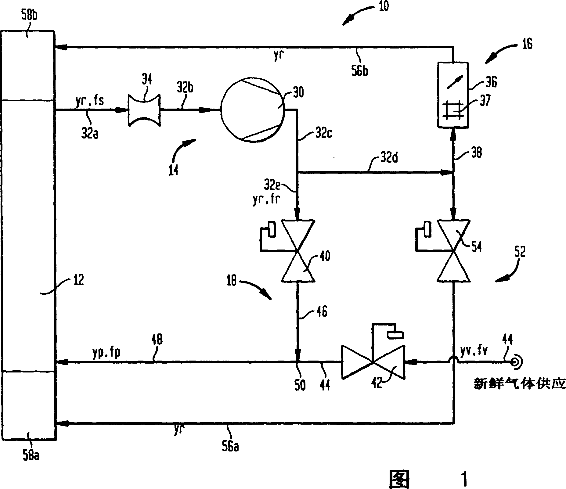
[0021] Referring to FIG. 1 , there is shown a system 10 for recovering and recirculating coolant gases such as helium, nitrogen, helium-nitrogen mixtures, helium-air mixtures, and the like. The system 10 includes a heat exchanger 12 , a coolant gas recovery section 14 , an analysis section 16 , and a coolant gas mixing section 18 operatively connected to each other.

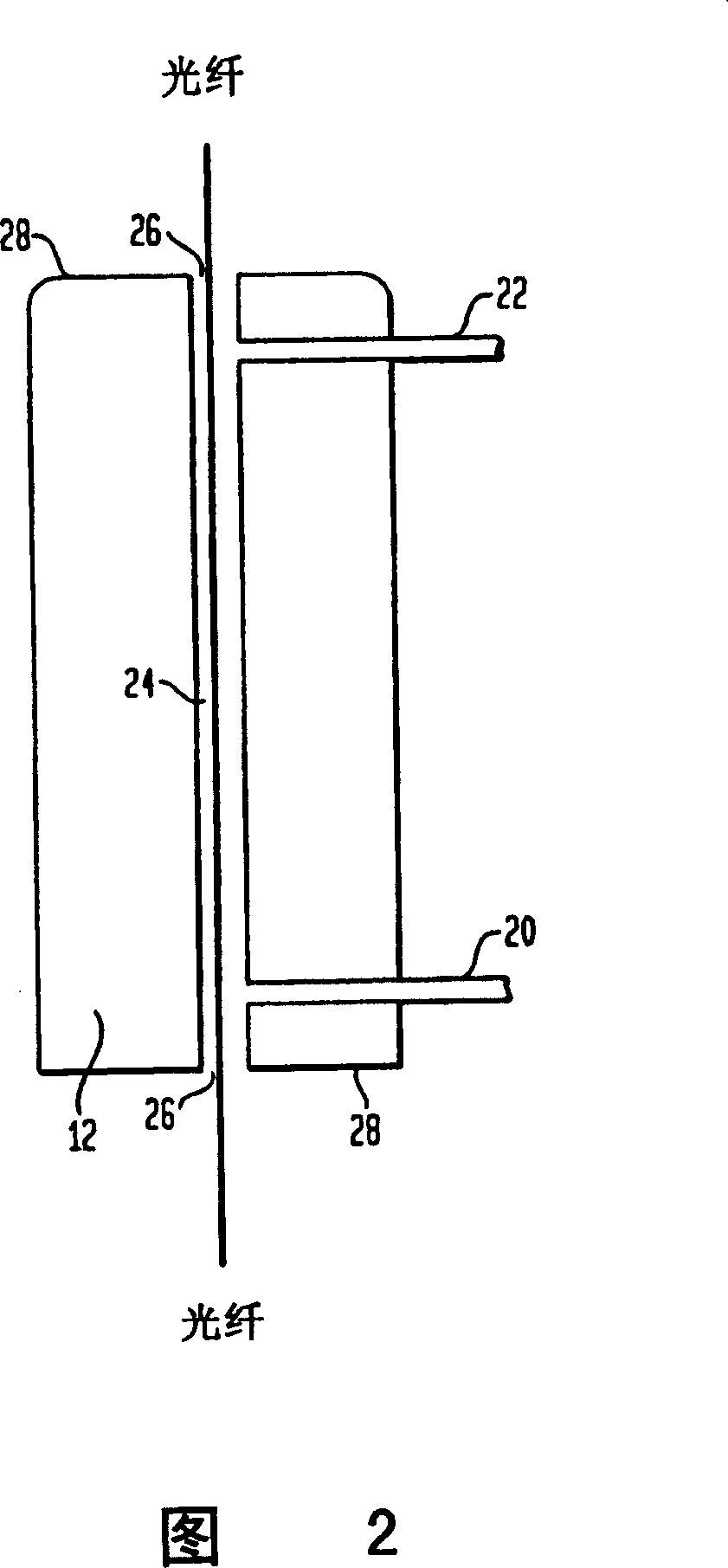
[0022] Heat exchanger 12, as shown in detail in FIG. heat exchanger or similar equipment). As shown in FIG. 2, the heat exchanger 12...


PUM


Abstract

An apparatus and method for recovering and recycling a coolant gas from a heat exchanger. The apparatus comprises a coolant gas recovery section, and analysis section, and a coolant gas blending section. The coolant gas recovery section recovers a coolant gas containing contaminants from the heat exchanger. The analysis section monitors a condition of an analysis portion of the recovered coolant gas. The coolant gas blending section operates to produce, based on the condition of the recovered coolant gas monitored by the analysis section, a blend coolant gas comprising a virgin coolant gas and a reclaimed coolant gas that comprises at least a portion of the recovered coolant gas. The blend coolant gas has a predetermined contaminant concentration and is recycled into the heat exchanger. Thus, the coolant gas is recovered from, and recycled to, the heat exchanger at the predetermined contaminant concentration without using a purification device.

Description

technical field [0001] The present invention generally relates to a coolant recovery and recycling apparatus. In one aspect, the invention relates to an apparatus for the recovery and recycling of helium associated with a heat exchanger. Background technique [0002] In the production of optical fibers, glass rods or "preforms" specially used to make optical fibers are processed in an optical fiber drawing system. Optical fiber drawing systems typically include a furnace, a heat exchanger, a coating applicator, a drying or curing oven and a mandrel such as that shown in European Patent Application No. 0079188. Initially, a glass rod is melted in a furnace, thus producing a fine, semi-liquid fiber. Next, the semi-liquid fibers are cooled and solidified as they flow through air and heat exchangers. Thereafter, the cooled, cured fiber can be coated in a coating applicator, dried in a curing oven or dryer, and drawn on mandrels. [0003] The control rate of fiber drawing gen...

Claims


Application Information

Patent Timeline
Patent Type & Authority Patents(China)
IPC IPC(8): C03B37/025C03B37/027G02B6/00G01N1/00C03B37/03C03B37/12F25D9/00
CPCC03B2205/57C03B37/02718C03B37/03
Inventor I·沙德利特斯基A·米克吕亚平
Owner BOC GRP INC
Features
  • R&D
  • Intellectual Property
  • Life Sciences
  • Materials
  • Tech Scout
  • Unparalleled Data Quality
  • Higher Quality Content
  • 60% Fewer Hallucinations
Learn More