Thermal synthesis apparatus and process

a technology of synthesis apparatus and process, applied in the direction of chemical/physical/physical-chemical stationary reactors, chemical/physical/physical-chemical processes, plasma techniques, etc., can solve the problems of limited success in today's economy, inability to transport energy resources economically and safely from those regions, and inability to convert natural gas to higher value hydrocarbons. , to achieve the effect of smooth acceleration and expansion of gases, reducing the kinetic temperature of gases, and reducing the yield of desired end products

Inactive Publication Date: 2004-11-23
BATTELLE ENERGY ALLIANCE LLC
View PDF62 Cites 140 Cited by
  • Summary
  • Abstract
  • Description
  • Claims
  • Application Information

AI Technical Summary

Benefits of technology

It is a further object of the invention to provide an improved process conversion efficiency and product yield in the thermal conversion of one or more reactants in a thermodynamically stable high temperature gaseous stream to a desired end product.
It is by including insulating layer 108 on reactor chamber 104, including injection line 112, and by carefully placing anode injector 110 closer to the arc that apparatus 100 is able to achieve the desired reactions at a high efficiency, even without the converging-diverging nozzle.

Problems solved by technology

Huge reserves of natural gas are known to exist in remote areas of the continental U.S., but this energy resource cannot be transported economically and safely from those regions.
Conversion of natural gas to higher value hydrocarbons has been researched for decades with limited success in today's economy.
Supplies from domestic and foreign oil reserves to produce these petrochemical based raw materials are declining, which puts pressure on the search for alternatives to the petrochemical based feed stock.
These costly endothermic processes are operated at high temperatures and high pressures.
Development of special catalysts for direct natural gas conversion process is the biggest challenge for the advancement of these technologies.
The conversion yields of such processes are low, implementing them is costly in comparison to indirect processes, and the technologies have not been proven.
Although in commercial use, the Huels process is only marginally economical because of the relatively low single pass efficiencies and the need to separate product gases from quench gases.
The plant-scale operation was limited to liquefied petroleum gas or liquid hydrocarbon distillates.
Reaction cracking of the methane occurs in the narrow annular space between the tubes where the temperature is 1900 to 2100 K. In operation, carbon formation in the annulus led to significant operational problems.
Unfortunately, the widespread use of titanium has been severely limited by its high cost.
The magnitude of this cost is a direct consequence of the batch nature of the conventional Kroll and Hunter processes for metal production, as well as the high energy consumption rates required by their usage.
The combined effects of the inherent costs of such processes, the difficulty associated with forging and machining titanium and, in recent years, a shortfall in sponge availability, have contributed to relatively low titanium utilization.
Presently, titanium sponge fines from the Kroll process are used, but a major drawback is their high residual impurity content (principally chlorides), which results in porosity in the final material.
Use of such existing powders involves a number of expensive purification and alloying steps as outlined above.
Although early thermodynamic calculations indicated that the reduction of titanium tetrachloride to metallic titanium by hydrogen could start at 2500 K, the system is not a simple one.
At such a high temperature, it was disclosed that while titanium tetrachloride vapor is effectively reduced by atomic hydrogen, the tendency of H.sub.2 to dissolve in or react with Ti is insignificant, the HCl formed is only about 10% dissociated, and the formation of titanium subchlorides could be much less favorable.

Method used


Image

  • Thermal synthesis apparatus and process
  • Thermal synthesis apparatus and process
  • Thermal synthesis apparatus and process

Examples


example 1

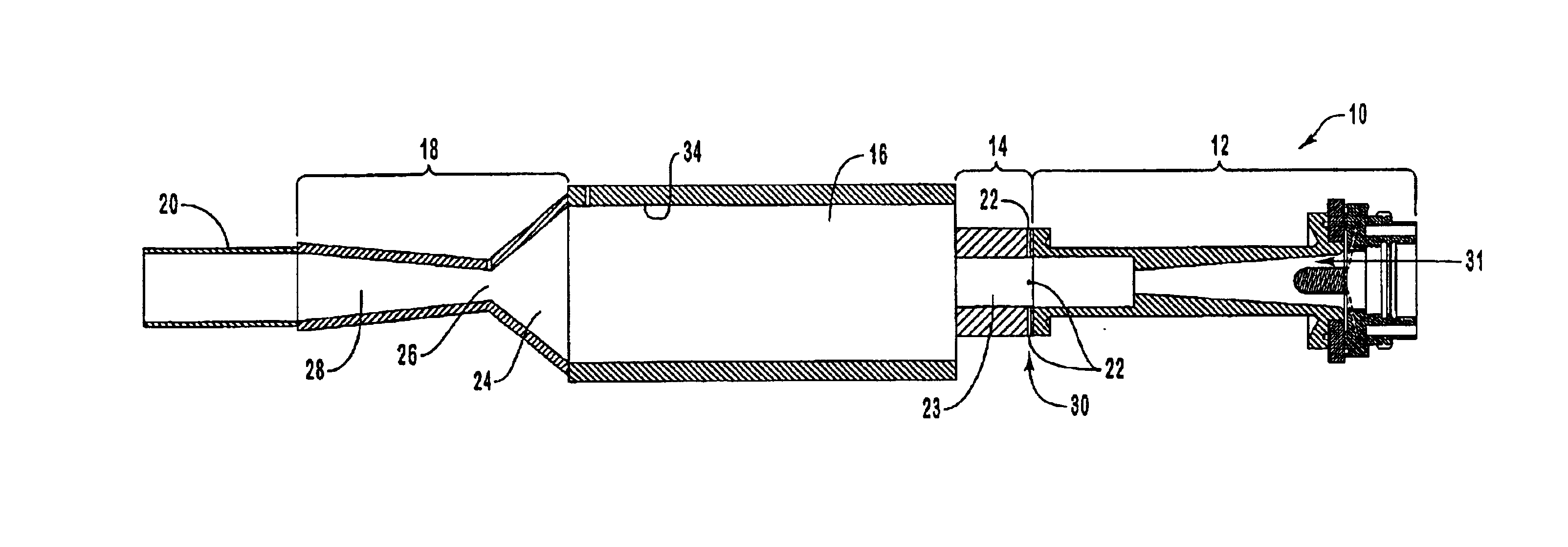
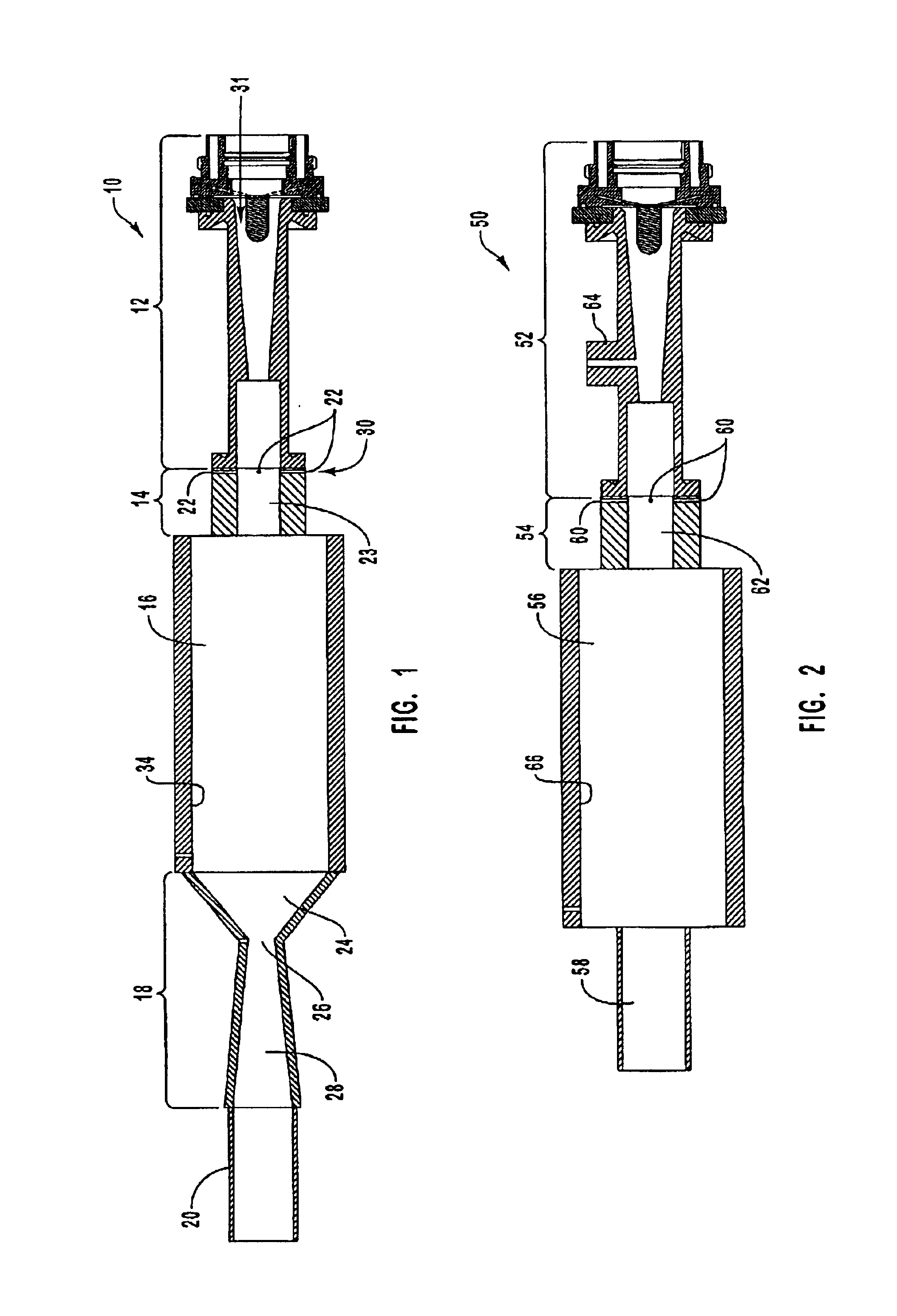
In this example the results of experiments with a converging-diverging nozzle are presented. Conversion efficiency as a function of the rate of methane injection is plotted in the graph of FIG. 5. In developing this data set the power deposited in the plasma was maintained constant at 60 kW and the plasma gas flow rates were constant at 160 slm Ar and 100 slm H.sub.2. The measured reactor pressure was relatively constant, varying between approximately 670 and 730 torr, depending on the rate of methane injection. Methane conversion was essentially complete, that is a conversion efficiency of 100%, at methane feed rates up to about 100 slm. At feed rates above 100 slm the conversion efficiency started to decline and dipped below approximately 95% at a feed rate of around 120 slm. The estimated bulk gas temperature in the reactor and corresponding residence time in the reactor is plotted in the graph of FIG. 6. This estimate was obtained from the measured system energy balance, the pla...

example 2

In this example the results of experiments without the use of a converging-diverging nozzle are presented. The conversion efficiency (.about.100% vs. 70%) yield, and selectivity (95% vs. 51%) of the present process demonstrated appear to be somewhat superior to the original Huels process. This may be due to better mixing, temperature uniformity, or more rapid quenching. The Huels product stream analysis as well as the laboratory scale results are summarized in Table 2.

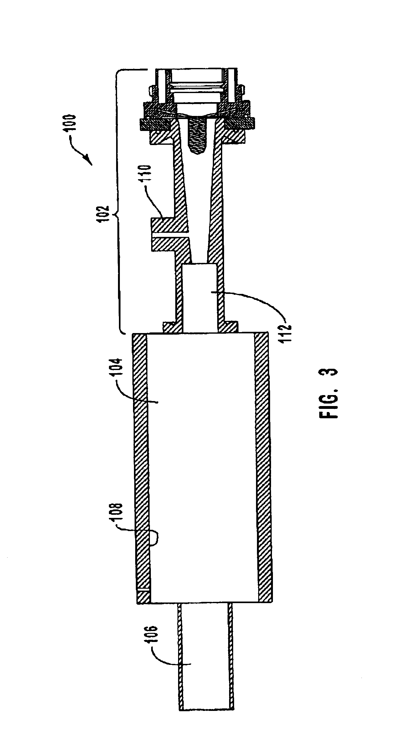
To assess the effect of rapid aerodynamic quenching a series of tests, identical to those reported in Example 1 were conducted, but without the converging-diverging nozzle. In these tests the system pressure was maintained at between 700 and 900 torr, approximately the same as the reactor pressure in the test series of Example 1. Conversion efficiency, yield, and normalized yield results are summarized in the graphs of FIGS. 12-14. The yield of other hydrocarbon species is summarized in the graph of FIG. 15.

The yield a...

example 3

Comprehensive data for a test run are provided in Tables 3-5 below. The test run was conducted without a converging-diverging nozzle. Table 3 presents a summary of the flow rates, power, measured torch thermal efficiency, nozzle geometry, and reactor and exit pressures.

Table 4 presents yield, volume rate, specific energy requirements (SER) and relative yield for the acetylene and hydrogen in the test. The column and row headings are generally sufficient to describe the data contained therein. Specifically, the column labeled Yield %: Qt meas. provides the yield of acetylene and hydrogen from methane feedstock and measured conversion efficiency. The acetylene yield is the percent of the carbon in the methane feedstock that ends up in acetylene and the hydrogen yield is the percent of the hydrogen in the methane feedstock that ends up as elemental hydrogen. Qt denotes measurements based on the downstream turbine flow meter. The column labeled Yield %: Qt At std. provides the yield of ...


PUM

PropertyMeasurementUnit
temperatureaaaaaaaaaa

Abstract

An apparatus for thermal conversion of one or more reactants to desired end products includes an insulated reactor chamber having a high temperature heater such as a plasma torch at its inlet end and, optionally, a restrictive convergent-divergent nozzle at its outlet end. In a thermal conversion method, reactants are injected upstream from the reactor chamber and thoroughly mixed with the plasma stream before entering the reactor chamber. The reactor chamber has a reaction zone that is maintained at a substantially uniform temperature. The resulting heated gaseous stream is then rapidly cooled by passage through the nozzle, which "freezes" the desired end product(s) in the heated equilibrium reaction stage, or is discharged through an outlet pipe without the convergent-divergent nozzle. The desired end products are then separated from the gaseous stream.

Description

1. Field of the InventionThe present invention relates generally to a thermal synthesis process. In particular, the present invention relates to methods and apparatus for thermal conversion of reactants in a thermodynamically stable high temperature gaseous stream to desired end products, such as either a gas or ultrafine solid particles.2. Relevant TechnologyNatural gas (where methane is the main hydrocarbon) is a low value and underutilized energy resource in the United State. Huge reserves of natural gas are known to exist in remote areas of the continental U.S., but this energy resource cannot be transported economically and safely from those regions. Conversion of natural gas to higher value hydrocarbons has been researched for decades with limited success in today's economy. Recently, there have been efforts to evaluate technologies for the conversion of natural gas (which is being flared) to acetylene as a feed stock for commodity chemicals. The ready availability of large na...

Claims


Application Information

Patent Timeline
Patent Type & Authority Patents(United States)
IPC IPC(8): B01J19/08B01J19/26C01B3/34C01B3/24C01B3/00C01B31/00C01B7/00C01B31/18C07C2/76C01B7/03C07C2/00C01G1/02C22B4/00C22B4/08C22B34/12C22B34/00H05H1/24C01B32/40
CPCB01J19/088B01J19/26H05H1/24C01B3/24C01B3/342C01B7/035C01B31/18C01G1/02C07C2/76C22B4/005C22B4/08C22B34/12C22B34/1286C22B34/129C07C11/24B01J2219/00094B01J2219/00119B01J2219/00155B01J2219/00159B01J2219/00162B01J2219/00166B01J2219/00245B01J2219/0809B01J2219/0828B01J2219/0869B01J2219/0871B01J2219/0875B01J2219/0883B01J2219/0886B01J2219/0898C01P2002/87H05H1/34C01B32/40H05H1/3484
Inventor FINCKE, JAMES R.DETERING, BRENT A.
Owner BATTELLE ENERGY ALLIANCE LLC
Why Eureka
Try Eureka