Configurable system and method for cooling a room

a technology of cooling system and configuration, applied in the direction of ventilation system, heating type, lighting and heating apparatus, etc., can solve the problems of difficult to modify the cooling system accordingly, the cooling characteristic of existing cooling system is often a costly adventure, and the rigidity of the cooling system of electronic equipment, etc., to achieve greater and greater efficiencies

Inactive Publication Date: 2003-05-06
VERTIV CORP
View PDF12 Cites 142 Cited by
  • Summary
  • Abstract
  • Description
  • Claims
  • Application Information

AI Technical Summary

Benefits of technology

The growth of the computer industry and telephony over the past few decades has been phenomenal. The integration of these technologies, for example, in telecommunications switching systems, has lead to greater and greater efficiencies as larger numbers of communications are handled by fewer components, which are typically housed in a central control room.
Floor-based cooling systems present additional difficulties other than structural rigidity. For instance, floor-based cooling systems that do not utilize conduits for passing cooled air occupy more area so that equipment cabling and other obstructions do not cause uneven air distribution or a reduction in air pressure. Such systems require the equipment cabling to be plenum rated, thereby increasing system cost. Floor-based cooling systems also possess the tendency to distribute noise and vibrations, which may effect the operation of the equipment to be cooled.
The present invention overcomes the above-discussed shortcomings and satisfies a significant need for a cooling system for cooling a room having one or more heat generating objects. The cooling system includes at least one heat exchanger disposed beneath the floor and extending substantially entirely between the walls of the room, and a fan unit disposed between the at least one heat exchanger and the floor and being selectively positioned along the at least one heat exchanger so as to draw air therefrom and blow the drawn air into the room, e.g., to a room portion having heat dissipation problems. By positioning the fan unit along the heat exchanger to adjustably provide a cooled airflow proximally to heat generating objects in the room, the present invention provides a reconfigurable cooling system that is selectively customized to particular room cooling requirements. The above reconfigurable system is also applicable to a heat exchanger installed in the ceiling above the various heat generating objects, enabling dual heat exchanging in order to further improve thermal efficiency.
The present invention is also directed to a system better exploiting the reconfigurability aspects of the above embodiments. In particular, through modularization of the fan units and heat exchangers, cooling difficulties in large rooms may be addressed in an economic manner. The interchangeability and interlinkage of the components would also permit easier repair and less downtime.

Problems solved by technology

One problem inherent with many existing cooling systems for electronic equipment is rigidity.
In the event the temperature characteristics within the temperature-cooled room changes, such as by the equipment being moved within the room or by additional equipment being added therein, it is very difficult to modify the cooling system accordingly.
Consequently, altering the cooling characteristics of existing cooling systems frequently proves a costly adventure.
Floor-based cooling systems present additional difficulties other than structural rigidity.
Such systems require the equipment cabling to be plenum rated, thereby increasing system cost.
Floor-based cooling systems also possess the tendency to distribute noise and vibrations, which may effect the operation of the equipment to be cooled.
In addition, floor-based and other existing cooling systems have a rather limited cooling capability.
Although perhaps adequate for some current systems, cooling systems having such heat densities may not effectively cool many of today's equipment, such as state-of-the-art computational equipment.
As is readily apparent, if equipment is not effectively cooled, the internal temperature of the electronic components in the equipment substantially increases, thereby leading to significantly reduced system performance and, in some cases, total system failure.
If a cooling system inefficiently cools the equipment, either the equipment may fail due to increased operating temperature or the costs for cooling the equipment may be unnecessarily high.

Method used


Image

  • Configurable system and method for cooling a room
  • Configurable system and method for cooling a room
  • Configurable system and method for cooling a room

Examples


Embodiment Construction

The present invention will now be described more fully hereinafter with reference to the accompanying drawings in which a preferred embodiment of the invention is shown. This invention may, however, be embodied in many different forms and should not be construed as being limited to the embodiment set forth herein. Rather, the embodiment is provided so that this disclosure will be thorough and complete, and will fully convey the scope of the invention to those skilled in the art.

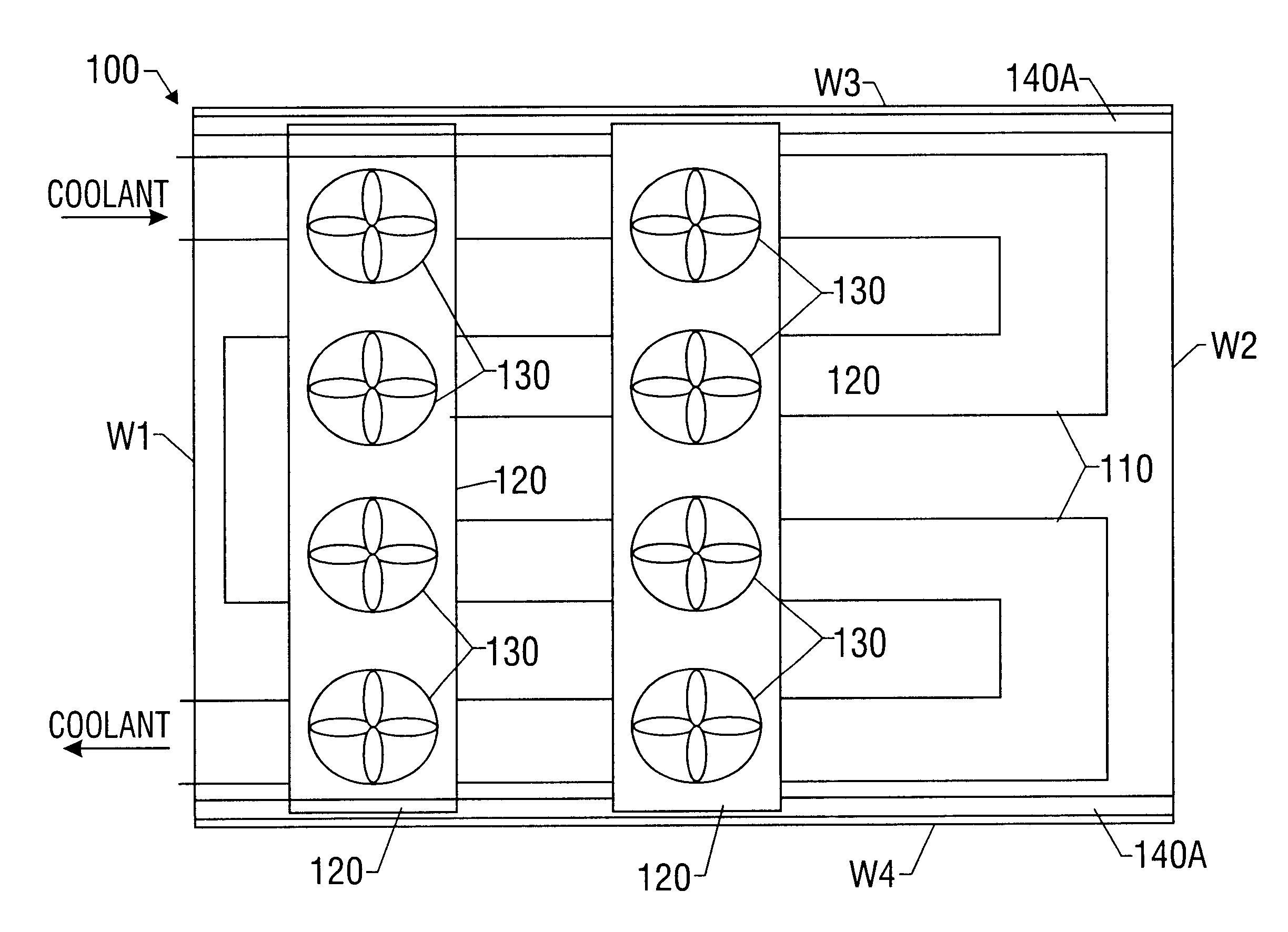
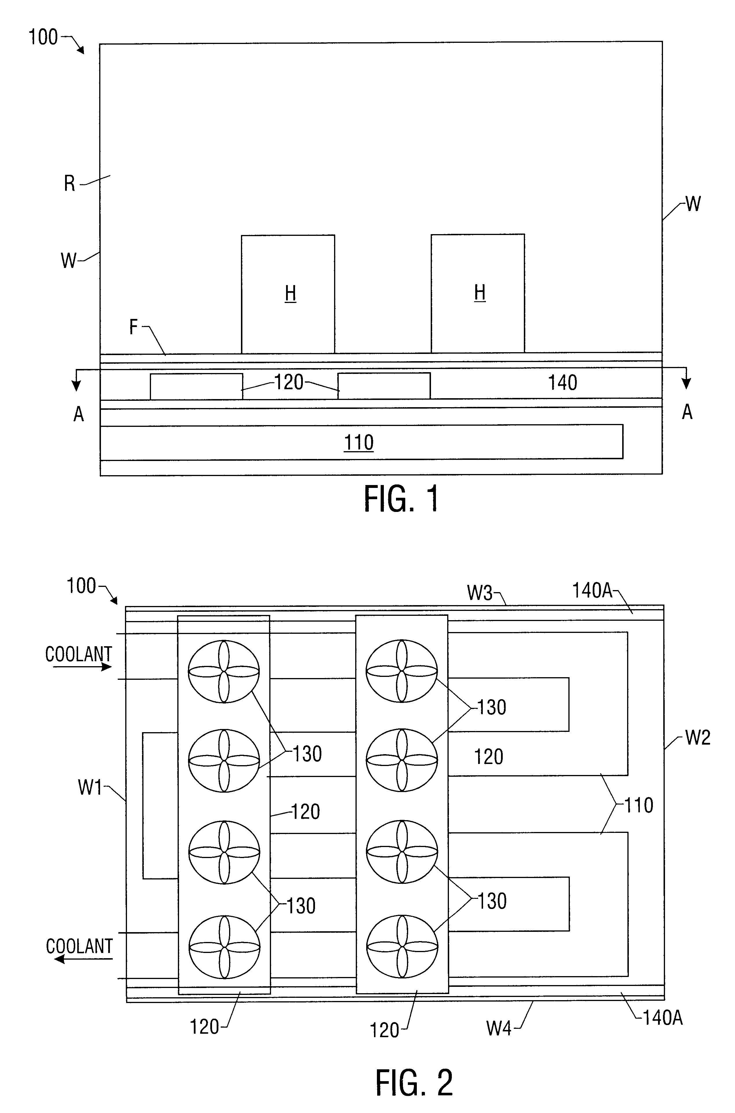
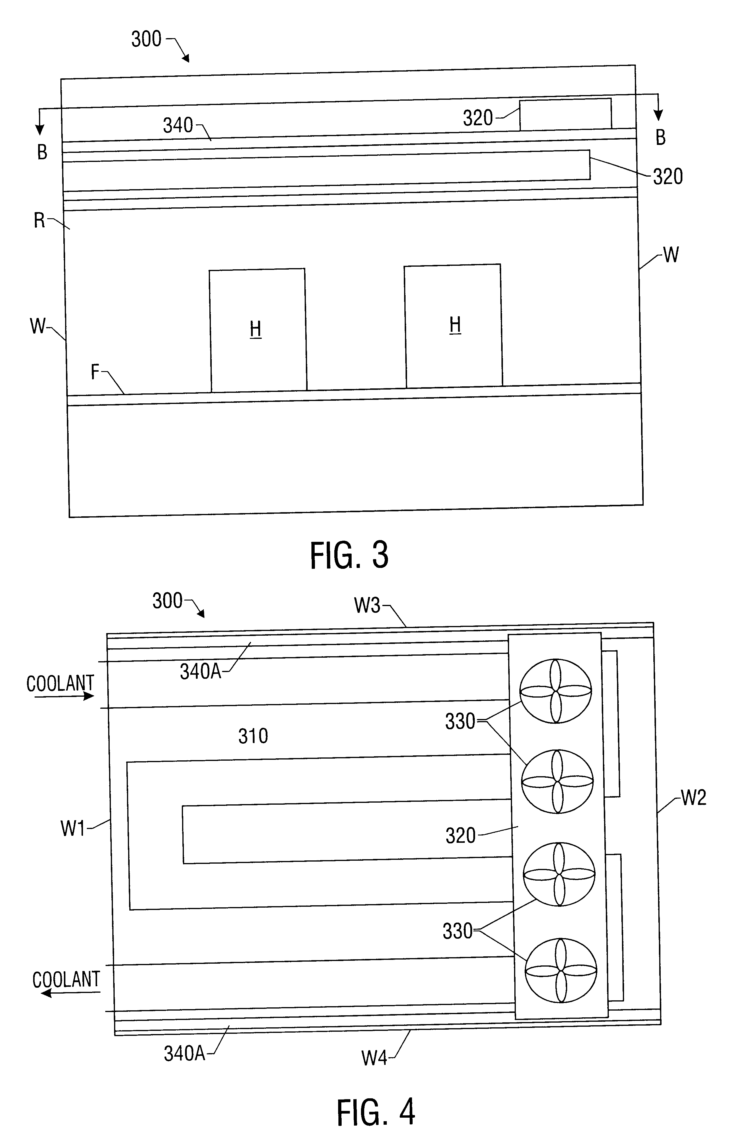
Referring to FIGS. 1-3, there is shown a cooling system, generally designated by the reference numeral 100, according to an embodiment of the present invention. Cooling system 100 is adapted to provide cooled air to a room, generally designated by the reference symbol R, such as a room having electronic equipment or other heat generating objects H therein. Room R has a raised floor F that allows air to pass therethrough, such as a floor F having a grid-like pattern, permitting air to permeate therethrough.

Coo...


PUM


Abstract

A method and system are disclosed for cooling a room having one or more heat generating objects. A number of heat exchangers are disposed adjacent a floor or ceiling and extends substantially entirely or partially between the walls of the room. A fan unit is disposed adjacent the heat exchanger and draws or blows cooled air from the heat exchanger and directs the drawn air into the room. The fan unit is capable of being repositioned along a different portion of the heat exchanger so as to redefine the flow of cooled air into the room. The cooling system components are modularized enabling configuration of a number of components to cool a room.

Description

1. Technical Field of the InventionThe present invention relates to cooling systems for cooling a room having electronic equipment therein, and particularly to cooling systems for a computer room that are configurable to allow customized air flow in proximity to the location of computer equipment in the computer room.2. Background and Objects of the InventionThe growth of the computer industry and telephony over the past few decades has been phenomenal. The integration of these technologies, for example, in telecommunications switching systems, has lead to greater and greater efficiencies as larger numbers of communications are handled by fewer components, which are typically housed in a central control room.One problem inherent with many existing cooling systems for electronic equipment is rigidity. Many existing cooling systems are built into and / or under the flooring of a temperature-controlled room having equipment needing to be cooled. Such cooling systems employ fixed conduits...

Claims


Application Information

Patent Timeline
Patent Type & Authority Patents(United States)
IPC IPC(8): F24F1/00F24F5/00H05K7/20F24F1/0087
CPCF24F1/0007F24F1/0029F24F1/0033F24F5/001H05K7/20136Y02B30/746F24F2001/0048F24F2001/007F24F2221/14F24F11/0079F24F11/77F24F1/0057F24F1/00075Y02B30/70F24F1/0087
Inventor STAHL, LENNARTBELADY, CHRISTIAN L.
Owner VERTIV CORP
Why Eureka
Try Eureka