Distributed maximum power point tracking system, structure and process

a tracking system and maximum power point technology, applied in the direction of emergency protective circuit arrangement, emergency protection circuit arrangement for limiting excess voltage/current, etc., can solve the problems of large localized power dissipation, low voltage does not interface well with existing higher power systems, and strings of cells bring many complications, etc., to achieve easy determination of system status, increase operation time, and increase power production and efficiency

Active Publication Date: 2010-08-10
SOLAREDGE TECH LTD
View PDF15 Cites 146 Cited by
  • Summary
  • Abstract
  • Description
  • Claims
  • Application Information

AI Technical Summary

Benefits of technology

[0015]Distributed maximum power point tracking systems, structures, and processes are provided for power generation structures, such as for but not limited to a solar panel arrays. In an exemplary solar panel string structure, distributed maximum power point tracking (DMPPT) modules are provided, such as integrated into or retrofitted for each solar panel. The DMPPT modules provide panel level control for startup, operation, monitoring, and shutdown, and further provide flexible design and operation for strings of multiple panels. The strings are typically linked in parallel to a combiner box, and then toward an enhanced inverter module, which is typically connected to a power grid. Enhanced inverters are controllable either locally or remotely, wherein system status is readily determined, and operation of one or more sections of the system are readily controlled. The system provides increased operation time, and increased power production and efficiency, over a wide range of operating conditions.

Problems solved by technology

These low voltages do not interface well to existing higher power systems, so the cells are series connected, to create modules with higher terminal voltages.
These long strings of cells bring with them many complications.
A problem occurs when even a single cell in a PV array is shaded or obscured.
The shaded cell is reverse biased by the remaining cells in the string, while current continues to flow through the shaded cell, causing large localized power dissipation.
This power is converted to heat, which in turn lowers the panel's output power capability.
However, all the power from that sub-string is lost, while current flows in the bypass diode.
As well, the bypass diode wastes power from the entire string current, which flows through the panel.
The output voltage of the entire string is also negatively affected, causing an even larger imbalance in the system.
Conventional module MPP currents may become unbalanced for other reasons.
Because each PV panel in a series string is constrained to conduct the same current as the other PV panels in the string, the least efficient module sets the maximum string current, thereby reducing the overall efficiency of the array to the efficiency of this PV panel.
This is not always possible or desirable, such as for aesthetic or other architectural reasons.
However, it is not a true average, since there is a preference that leans towards the weakest link in the system.
This means that, even though some panels may be capable of supplying 100 percent of their rated power, the system will only harvest a fraction of that power, due to the averaging effect of the algorithm, and the current following through the weaker string, panel, and / or cells.

Method used


Image

  • Distributed maximum power point tracking system, structure and process
  • Distributed maximum power point tracking system, structure and process
  • Distributed maximum power point tracking system, structure and process

Examples


Embodiment Construction

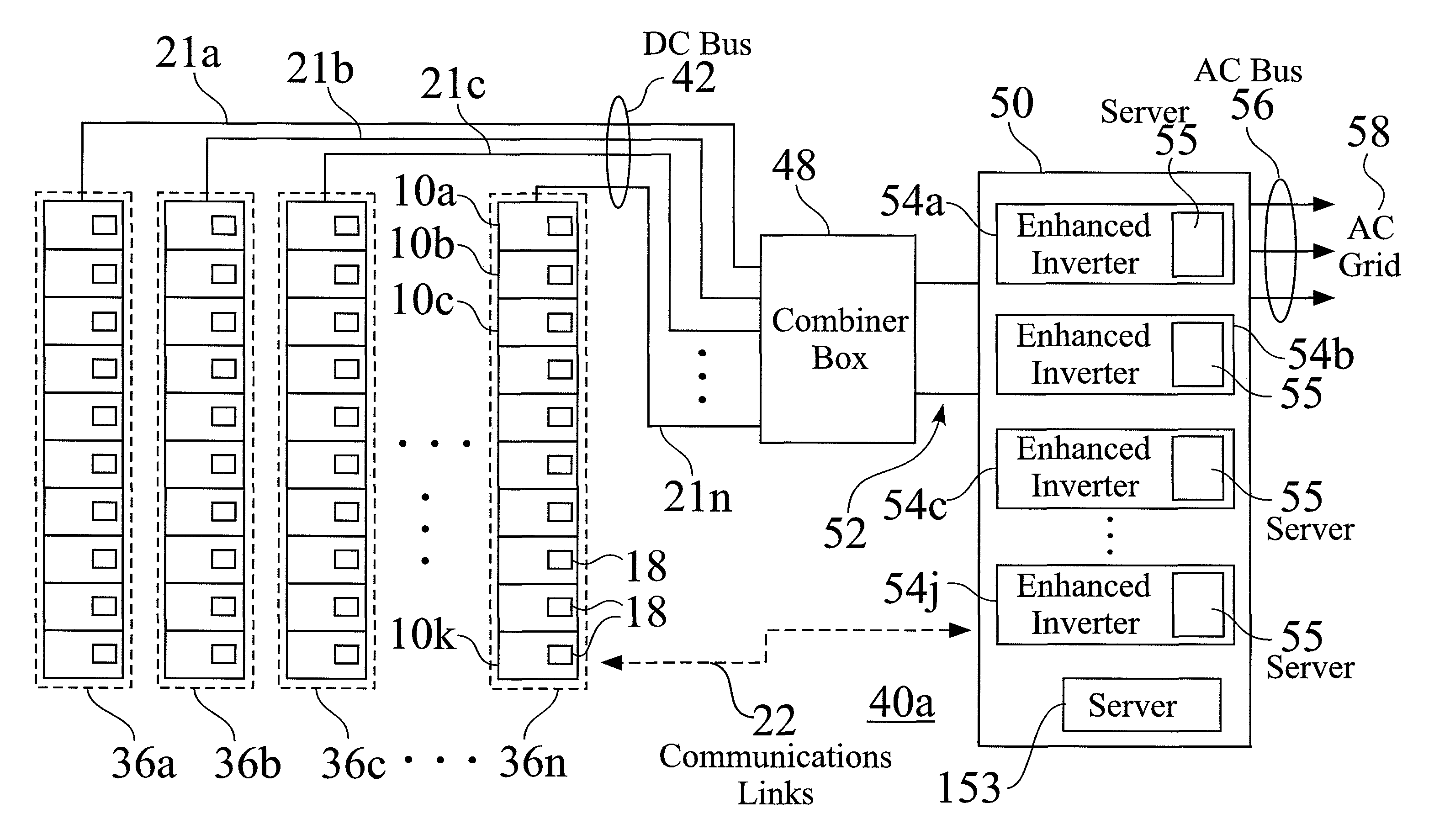
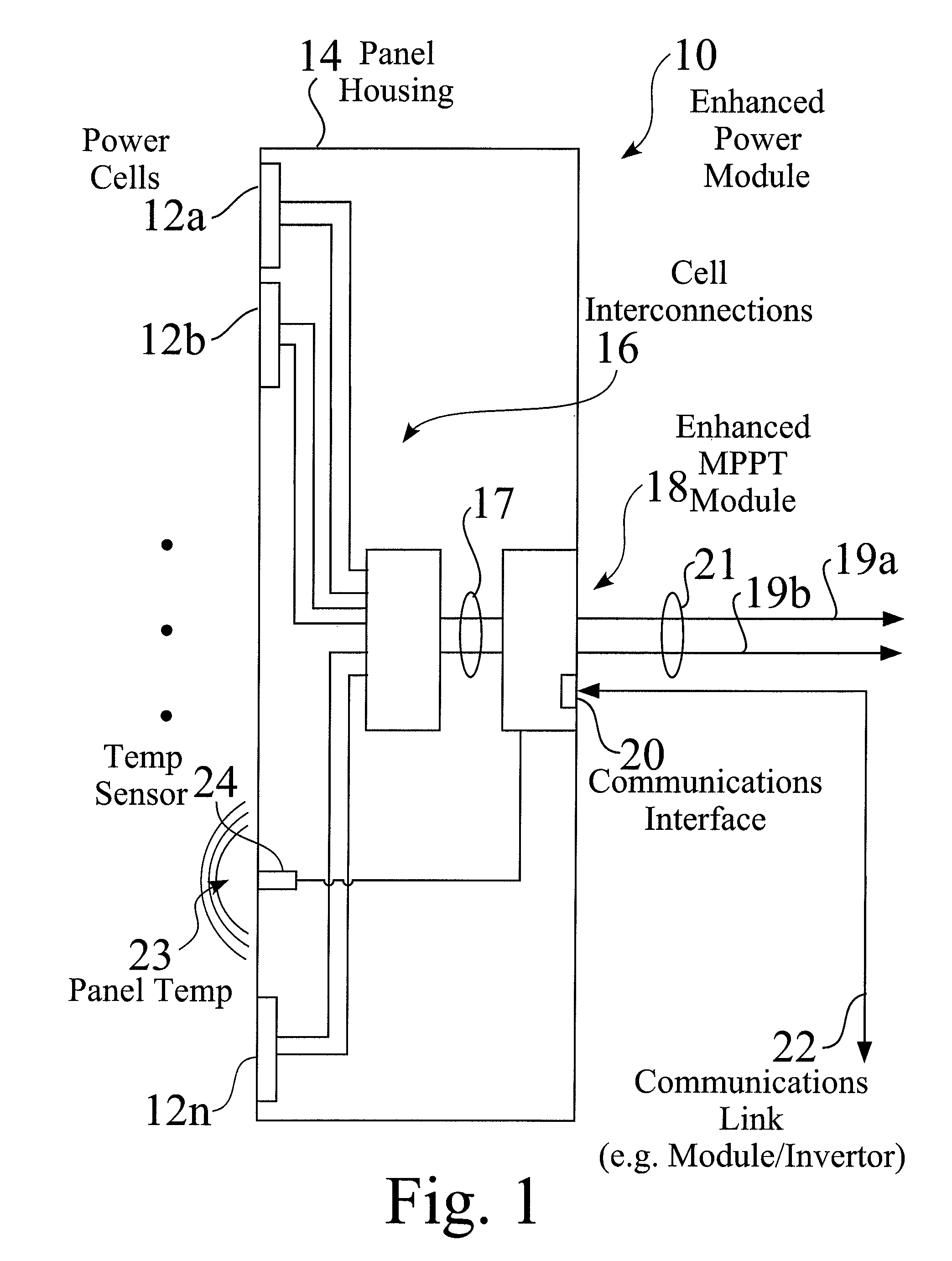
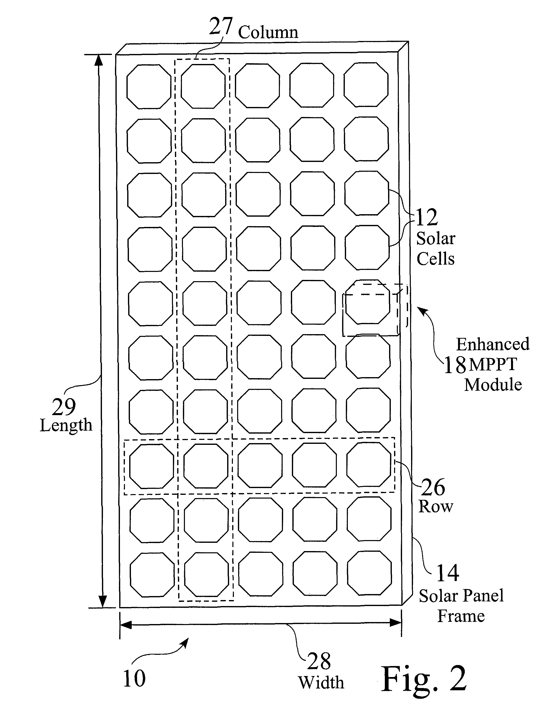
[0045]FIG. 1 is a schematic view of an exemplary enhanced power module 10 comprising a plurality of power cells 12, e.g. 12a-12n, such as but not limited to photovoltaic solar cells, fuel cells, and battery cells, connected 16,17 to a distributed maximum power point tracking (DMPPT) module 18. FIG. 2 is a schematic view of an exemplary enhanced power structure 10, e.g. an enhanced solar panel 10, comprising a plurality of solar cells 12 and a distributed maximum power point tracking module 18. FIG. 3 is a schematic view 30 of an exemplary photovoltaic solar cell having DC output power connections 17 to a DMPPT module 18. FIG. 4 is a schematic view of an exemplary solar array 34 comprising a plurality of enhanced solar panels 10, e.g. 10a-10k, arranged in a plurality of strings 36, e.g. 36a-36n.

[0046]The exemplary DMPPT module 18 seen in FIG. 1 has DC inputs 17, and a DC output 21, such as comprising a positive lead 19a and a negative lead 19b, The exemplary DMPPT module 18 also com...


PUM


Abstract

Distributed maximum power point tracking systems, structures, and processes are provided for power generation structures, such as for but not limited to a solar panel arrays. In an exemplary solar panel string structure, distributed maximum power point tracking (DMPPT) modules are provided, such as integrated into or retrofitted for each solar panel. The DMPPT modules provide panel level control for startup, operation, monitoring, and shutdown, and further provide flexible design and operation for strings of multiple panels. The strings are typically linked in parallel to a combiner box, and then toward and enhanced inverter module, which is typically connected to a power grid. Enhanced inverters are controllable either locally or remotely, wherein system status is readily determined, and operation of one or more sections of the system are readily controlled. The system provides increased operation time, and increased power production and efficiency, over a wide range of operating conditions.

Description

CROSS REFERENCE TO RELATED APPLICATION[0001]This Application claims priority to U.S. Provisional Application No. 60 / 908,361, entitled Distributed Multiple Power Point Tracking, filed 27 Mar. 2007.[0002]The aforementioned document is incorporated herein in its entirety by this reference thereto.FIELD OF THE INVENTION[0003]The present invention relates generally to the field of power inverter systems. More particularly, the present invention relates to distributed power system structures, operation and control, and enhanced inverter systems, structures, and processes.BACKGROUND OF THE INVENTION[0004]Solar power is a clean renewable energy resource, and is becoming increasingly important for the future of this planet. Energy from the Sun is converted to electrical energy via the photoelectric effect using many photovoltaic cells in a photovoltaic (PV) panel. Power from a PV panel is direct current (DC), while modern utility grids require alternating current (AC) power. The DC power fro...

Claims


Application Information

Patent Timeline
Patent Type & Authority Patents(United States)
IPC IPC(8): H02J3/14
CPCH02J3/385H01L31/02021H02H9/041Y02E10/50H02J2300/26H02J3/381Y02A30/60Y02E10/56H02J3/38
Inventor SHAVER, II, ARGIL E.NEWDOLL, RONALD M.
Owner SOLAREDGE TECH LTD
Why Eureka
Try Eureka