Cooling apparatus and method for an electronics module employing an integrated heat exchange assembly

a technology of heat exchange assembly and cooling apparatus, which is applied in the direction of cooling/ventilation/heating modification, power cables, cables, etc., can solve the problems of increased device temperature, thermal runaway conditions, increased heat production, etc., and achieves the effect of increasing power dissipation, increasing device temperature, and increasing device temperatur

Active Publication Date: 2006-06-15
IBM CORP
View PDF18 Cites 136 Cited by
  • Summary
  • Abstract
  • Description
  • Claims
  • Application Information

AI Technical Summary

Problems solved by technology

Failure to remove the heat thus produced results in increased device temperatures, potentially leading to thermal runaway conditions.
First, power dissipation, and therefore heat production, increases as device operating frequencies increase.
Further, as more and more devices are packed onto a single chip, power density (Watts / cm2) increases, resulting in the need to remove more power from a given size chip or module.
These trends have combined to create applications where it is no longer desirable to remove heat from modern devices solely by traditional air cooling methods, such as by using traditional air cooled heat sinks.
In particular, liquids such as refrigerants or other dielectric fluids (e.g., fluorocarbon fluid) exhibit relatively poor thermal conductivity and specific heat properties, i.e., when compared to liquids such as water or other aqueous fluids.
Water-based coolants, however, must be kept from physical contact with electronic devices and interconnects, since corrosion and electrical short circuit problems are likely to result from such contact.

Method used


Image

  • Cooling apparatus and method for an electronics module employing an integrated heat exchange assembly
  • Cooling apparatus and method for an electronics module employing an integrated heat exchange assembly
  • Cooling apparatus and method for an electronics module employing an integrated heat exchange assembly

Examples


Embodiment Construction

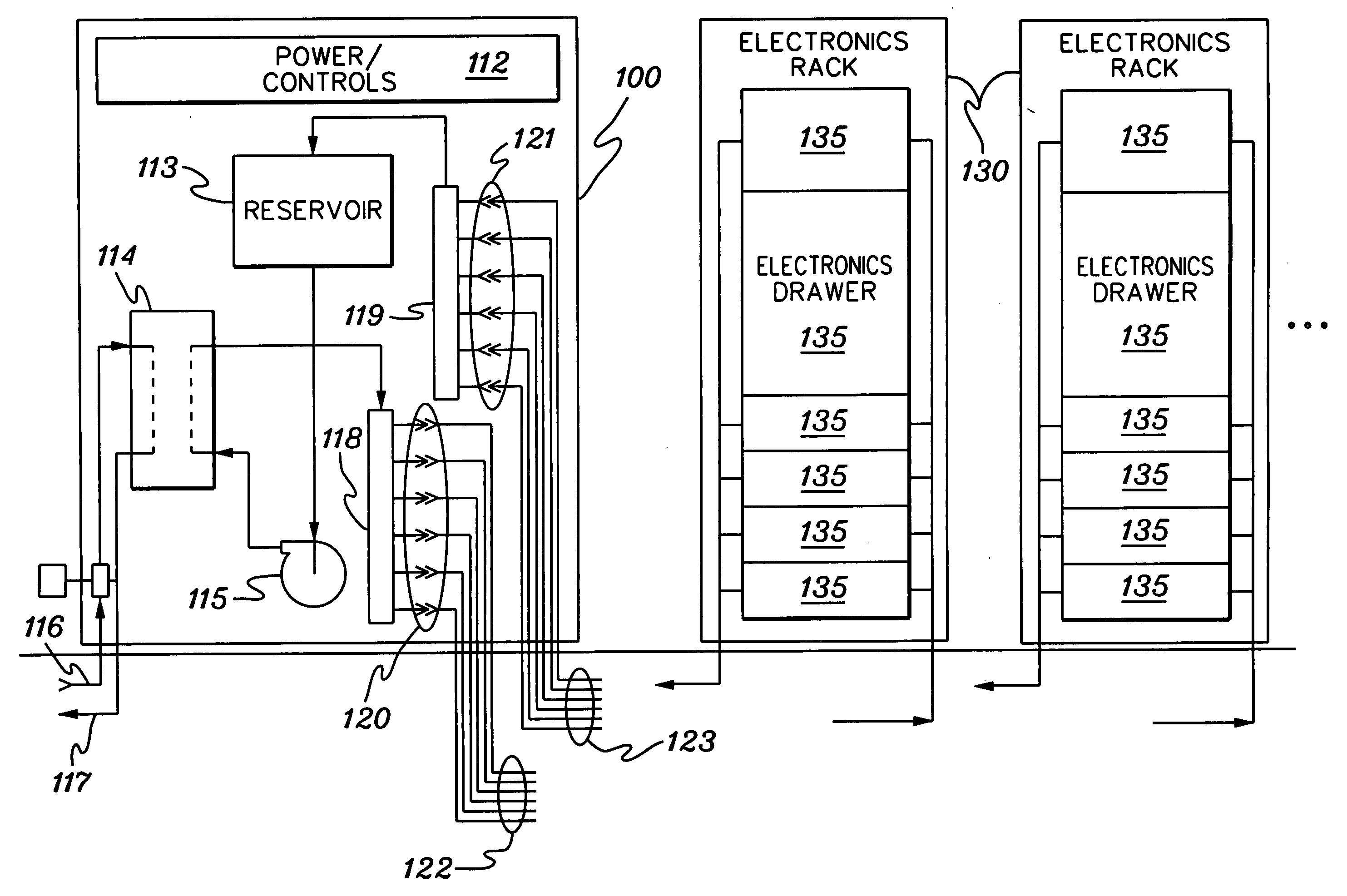
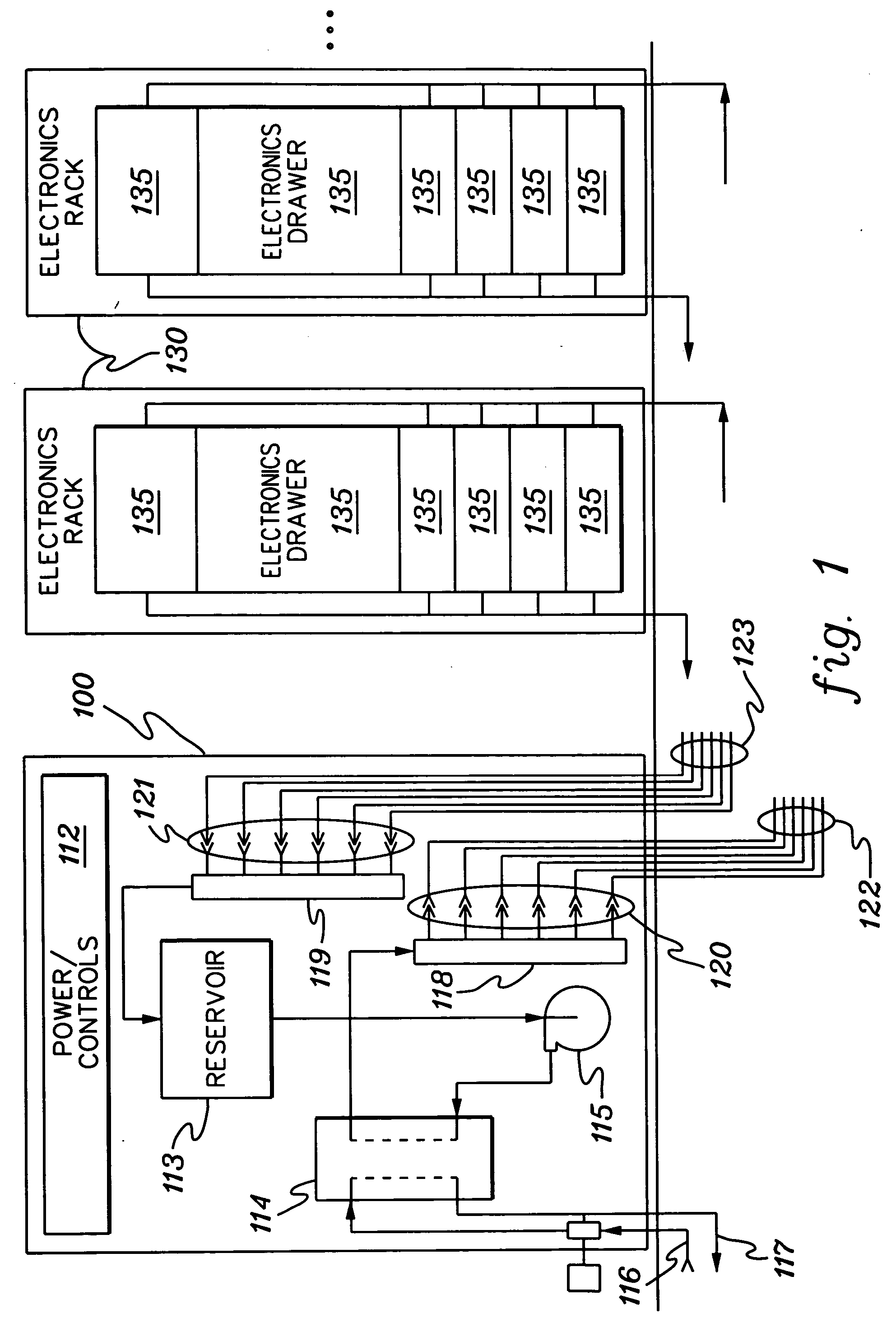
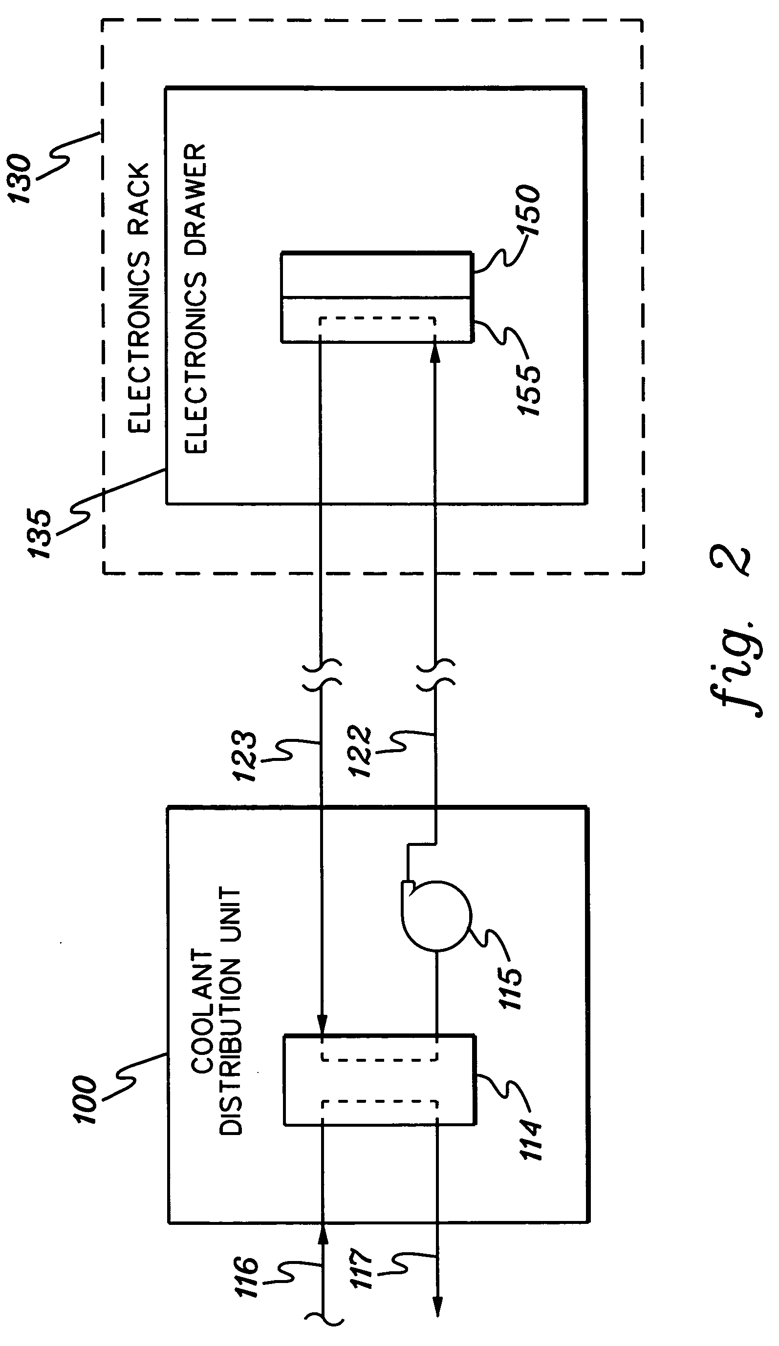
[0027] As used herein, “electronics subsystem” comprises any housing, compartment, drawer, blade, etc., containing one or more heat generating components of a computer system or other electronics system requiring cooling. The term “electronics rack” includes any frame, rack, blade server system, etc., having a heat generating component of a computer system or electronics system, and may be, for example, a stand alone computer processor having high, mid or low end processing capability. In one embodiment, an electronics rack may comprise multiple electronics subsystems, each having one or more heat generating components requiring cooling. Each heat generating component may comprise an electronics device, an electronics module, an integrated circuit chip, etc. As used herein, “micro-scaled cooling structure” means a cooling structure with a characteristic dimension of 200 micrometers (microns) or less.

[0028] One example of coolant within a cooling system in accordance with an aspect ...


PUM


Abstract

A cooling apparatus for an electronics assembly having a substrate and one or more electronics devices includes an enclosure sealably engaging the substrate to form a cavity, with the electronics devices and a heat exchange assembly being disposed within the cavity. The heat exchange assembly defines a primary coolant flow path and a separate, secondary coolant flow path. The primary coolant flow path includes first and second chambers in fluid communication, and the secondary flow path includes a third chamber disposed between the first and second chambers. The heat exchange assembly provides a first thermal conduction path between primary coolant in the first chamber and secondary coolant in the third chamber, and a second thermal conduction path between primary coolant in the second chamber and secondary coolant in the third chamber. The heat exchange assembly further includes coolant nozzles to direct primary coolant towards the electronics devices.

Description

CROSS-REFERENCE TO RELATED APPLICATIONS [0001] This application contains subject matter which is related to the subject matter of the following applications, each of which is assigned to the same assignee as this application and each of which is hereby incorporated herein by reference in its entirety: [0002]“Cooling System And Method Employing A Closed Loop Coolant Path And Micro-Scaled Cooling Structure Within An Electronics Subsystem Of An Electronics Rack,” Campbell et al., Serial No. ______, co-filed herewith (Attorney Docket No. POU920040172US1); [0003]“Cooling Apparatus For An Electronics Subsystem Employing A Coolant Flow Drive Apparatus Between Coolant Flow Paths,” Campbell et al., Serial No. ______, co-filed herewith (Attorney Docket No. POU920040171US1); and [0004]“Electronic Device Substrate Assembly With Multi-Layer Impermeable Barrier and Method of Making,” Chu et al., Ser. No. 10 / 197,661, filed Jul. 17, 2002, and published as U.S. Publication No. US 2004 / 0812914 A1, on...

Claims


Application Information

Patent Timeline
Patent Type & Authority Applications(United States)
IPC IPC(8): H05K7/20
CPCH05K7/20781H05K7/2079
Inventor CAMPBELL, LEVI A.CHU, RICHARD C.ELLSWORTH, MICHAEL J. JR.IYENGAR, MADHUSUDAN K.SCHMIDT, ROGER R.SIMONS, ROBERT E.
Owner IBM CORP
Why Eureka
Try Eureka