Texturing machine

A texturing machine, crimping technology, applied in the direction of textiles and paper making, to achieve the effect of simplifying the connection

Inactive Publication Date: 2007-06-20
OERLIKON TEXTILE GMBH & CO KG
View PDF5 Cites 0 Cited by
  • Summary
  • Abstract
  • Description
  • Claims
  • Application Information

AI Technical Summary

Problems solved by technology

However, the change of the thread guide basically has the disadvantage that the processing device arranged ahead or behind along the filament flow must be included in the changed thread guide.

Method used


Image

  • Texturing machine
  • Texturing machine
  • Texturing machine

Examples


Embodiment Construction

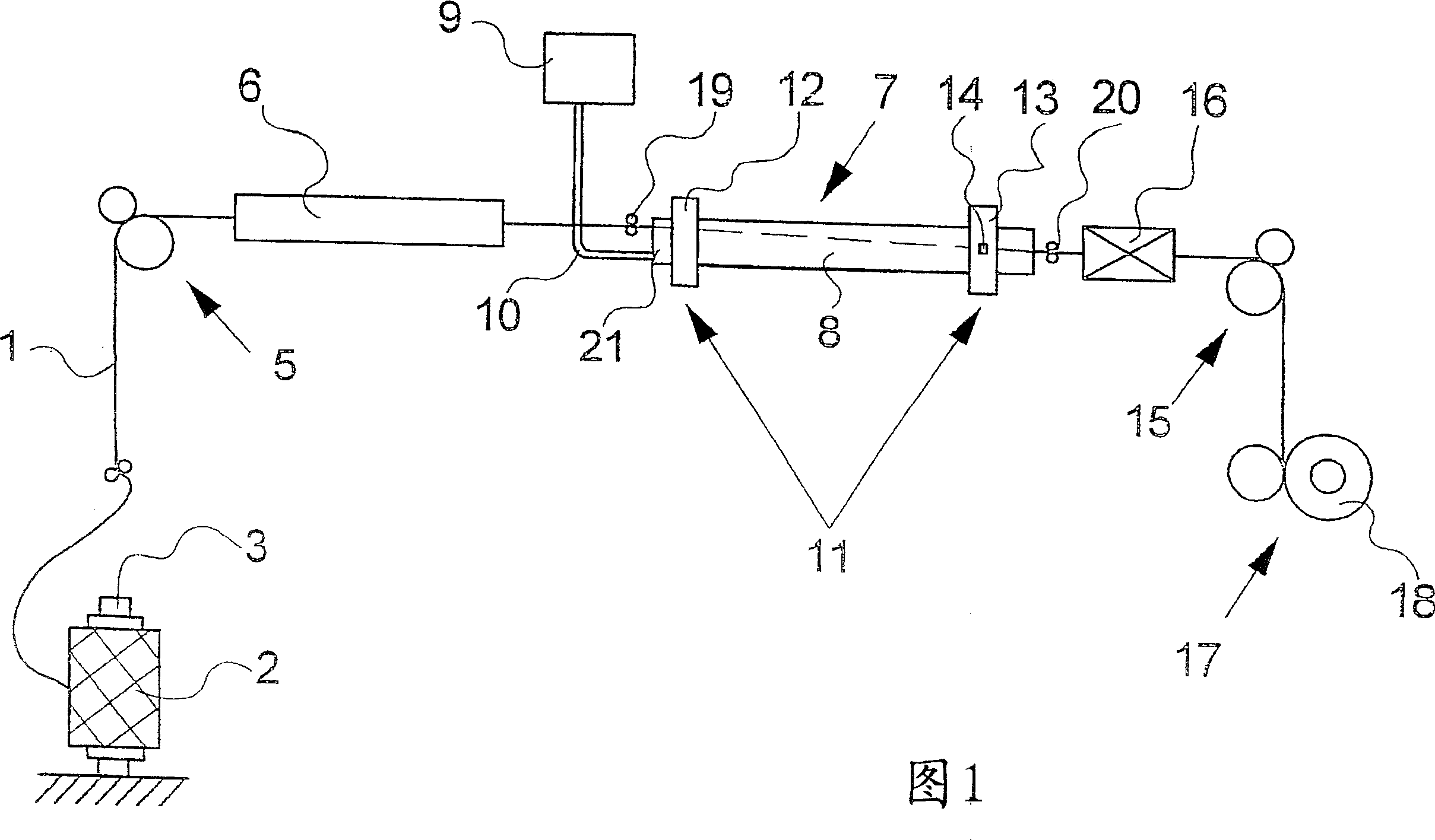
[0018] Figure 1 schematically shows the structure of a station in a crimp texturing machine. The crimp texturing machine has many stations, among which the multi-station processing unit is fixed on one or more stands. In order to crimp the filament 1, a station contains at least a first conveying device 5, a heating device 6, a cooling device 7, a false twister 16, a second conveying device 15 and a winding device 17, wherein The processing units are arranged in sequence to form a filament process. Here the filaments 1 are withdrawn from the feed bobbin 2 by the first conveying device 5 . Feed bobbins 2 are inserted on a mandrel 3 of the creel (not shown here). The first delivery device 5 guides the filament 1 into the so-called false twist zone, which extends as far as the false twister 16 . False twist is produced in the filament 1 by the false twister 16 , the false twist is traced back into the filament in the false twist zone and is then fixed in the heating device 6 a...


PUM


Abstract

The invention relates to a texturing machine for false twist texturing a thread. To this end, the texturing machine comprises at least one first delivery device, a heating device, a cooling device, a false twist unit, a second delivery device, and a coiling device. The cooling device comprises a cooling tube on the outer surface of which the thread is guided with contact along a helical cooling stretch which is formed on the circumference of the cooling tube. According to the invention, the cooling tube is embodied in a mobile manner in such a way that the length of the cooling stretch can be modified.

Description

technical field [0001] The invention relates to a crimp texturing machine for false twist crimp texturing of filaments. Background technique [0002] A crimp texturing machine of this type is known from EP0853150. [0003] In the known texturing machines the smooth filaments fed are texturized by a false twisting process. For this purpose, the false twist in the filament produced by the false twister is fixed by heat treatment and subsequent cooling. A cooling tube is used for cooling the false twisted filaments, over the surface of which the filaments run helically. In order to vary the cooling path over the surface of the cooling tube depending on the type of thread, texturing machines are known which have movable yarn guides which change the entry and exit points of the filament relative to the circumference of the cooling tube. In principle, however, a change in the thread guide has the disadvantage that treatment devices arranged upstream or downstream along the thre...

Claims


Application Information

Patent Timeline
IPC IPC(8): D02J13/00D02G1/02
CPCD02J13/003D02G1/0266
Inventor 沃尔夫冈-彼得·芬克
Owner OERLIKON TEXTILE GMBH & CO KG
Why Eureka
Try Eureka