Sunroof apparatus for vehicle

A technology for vehicles and sunroofs, which is applied in the field of position adjustment of the ceiling, can solve the problems of applying impacts, etc., and achieve the effects of weight reduction, compact size, and reduced operating noise

Inactive Publication Date: 2007-07-04
HONDA MOTOR CO LTD
View PDF6 Cites 0 Cited by
  • Summary
  • Abstract
  • Description
  • Claims
  • Application Information

AI Technical Summary

Problems solved by technology

[0011] Thus, in the prior art, if the ceiling is manually opened or closed with forc

Method used


Image

  • Sunroof apparatus for vehicle
  • Sunroof apparatus for vehicle
  • Sunroof apparatus for vehicle

Examples


Embodiment Construction

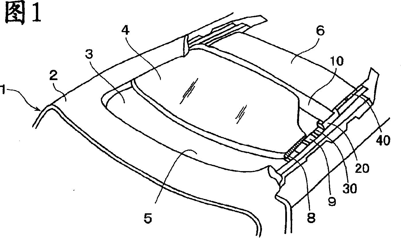
[0041]Figure 1 is a perspective view showing a sunroof arrangement according to the invention in the roof of a vehicle; the sunroof arrangement is constructed such that the opening 3 in the roof 2 of the vehicle 1 can be a sliding panel (roof) made of glass 4 is opened and closed at will, and the ceiling 6 in the opening 5 located on the cabin side corresponding to the opening 3 covers the lower side of the sliding panel 4, so that the sliding panel can be opened and closed at will.

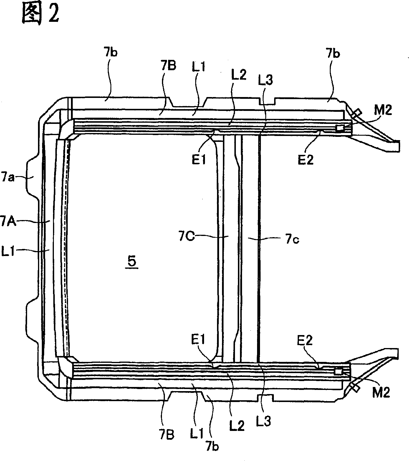
[0042] On the cabin side of the opening 3 in the roof 2 there are mounting brackets 7A, 7B and 7B and reinforcing brackets 7C, as shown in Figure 2, the mounting brackets 7A, 7B and 7B extend along the front and sides, and the reinforcing brackets 7C are connected The brackets 7B on both sides, the middle of 7B. These brackets 7A to 7C define an opening 5 on the side of the passenger compartment, which corresponds to the opening 3 . Brackets 7A to 7C are mounted to the underside of the roof 2 ar...


PUM


Abstract

A sunroof apparatus with a sliding panel freely opening and closing an opening of a roof in a vehicle, a movable drain arranged below a rear end in the panel and moving forward and rearward interlocking with a forward and rearward movement of the panel, and a sunshade covering a lower side of the sliding panel and freely opening and closing. A holding means for the sunshade is constructed by forming sliding grooves in frames in both sides extending along a longitudinal direction in a side of a passenger room of the opening, forming a notch at a predetermined position of the groove L3 fitting front and rear sliders to which the sunshade is mounted, and integrally forming an engagement piece made of elastic member and fitted to the notch in the rear slider. Further, a position regulating means, at the time of manually closing the sunshade in a state in which the panel is half open or fully open and at the time of manually opening the sunshade in a closed state of the panel, is constructed by integrally forming a stopper protruding to an upper side of the groove L2 in a slider fitted to the groove L3, to which the movable drain is mounted.

Description

technical field [0001] The invention relates to a solar sunroof device located on the top of a vehicle, in particular to the position adjustment of the sunroof in the sun roof device. Background technique [0002] A well-known conventional sunroof device is capable of freely opening and closing an opening at the roof of a vehicle by a sliding panel, and can be opened and closed at will by covering the lower side of the sliding panel with a sunroof in the opening at the side of a passenger cabin. [0003] The mounting brackets are located on both sides of the vehicle roof opening on the cabin side, and the slide plates (roof) are mounted to the front and rear plate-like slides, which are slidably connected, for example, by pin connections or cam connections, respectively. Fits to the plate runner formed in the mounting bracket. [0004] The slide plates are driven by push-pull cables mounted to the rear plate-like slide (plate drive slide), the slide plates can each be posit...

Claims


Application Information

Patent Timeline
IPC IPC(8): B60J7/00B60J7/02B60J7/057
CPCB60J7/0573B60J7/0084B60J7/003B60J7/022
Inventor 上原达明堀田贡市大西正治田村道生小原龙也
Owner HONDA MOTOR CO LTD
Why Eureka
Try Eureka