Needle-bar travel regulating device

A technology for adjusting device and needle bar stroke, which is applied to the needle seat of sewing machine, textile and papermaking, sewing equipment, etc., which can solve the problems of excessive processing costs and achieve good workability

Inactive Publication Date: 2007-07-11
JUKI CORP
View PDF6 Cites 0 Cited by
  • Summary
  • Abstract
  • Description
  • Claims
  • Application Information

AI Technical Summary

Problems solved by technology

[0007] However, the device disclosed in the above-mentioned gazette has the problem that since the crankshaft is protrudingly provided with an engaging protrusion, and at the same time, a positioning ring is provided on the eccentric pin, an engaging groove must be formed, so much processing cost is required.

Method used


Image

  • Needle-bar travel regulating device
  • Needle-bar travel regulating device
  • Needle-bar travel regulating device

Examples


Embodiment Construction

[0043] Embodiments of the present invention will be described in detail below with reference to the drawings.

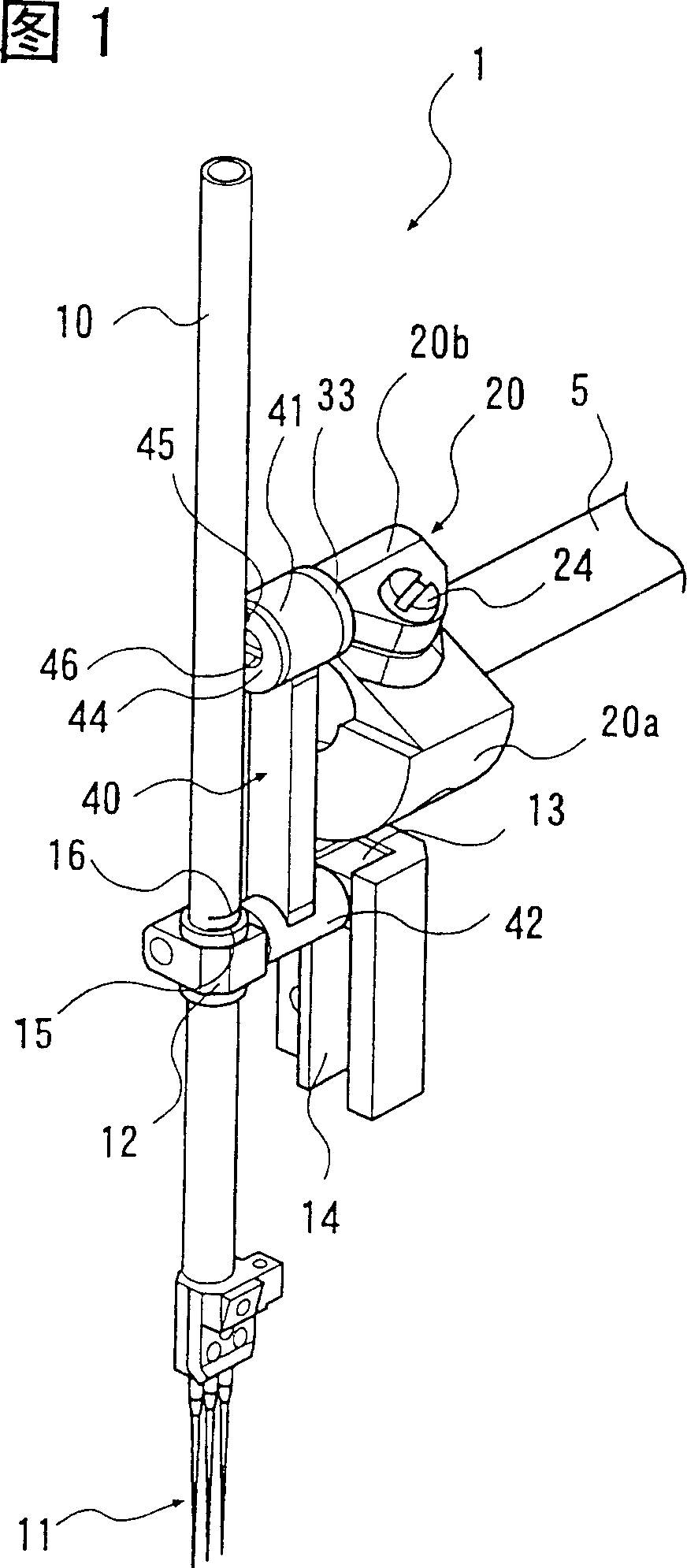
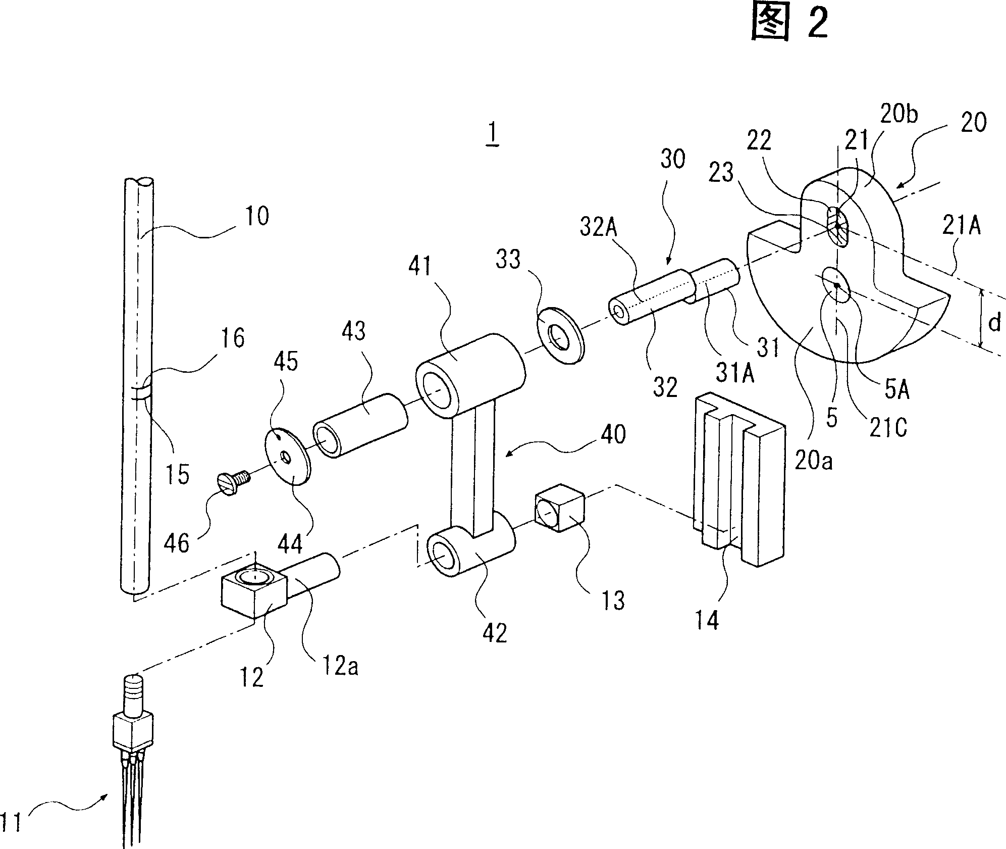
[0044] The needle bar stroke adjustment device 1 of the embodiment of the present invention is shown in Fig. 1 and Fig. 2, possesses: the crankshaft 20 that is fixed on the upper shaft 5; The eccentric pin 30 that one end is fixed on the crankshaft 20; A connecting rod 40 connected to the needle bar 10 at one end.

[0045] The upper shaft 5 is centered on the shaft center 5A shown in FIG. 2, and is driven to rotate around the shaft by a sewing machine motor not shown in the figure. A crankshaft 20 is fixed to the upper shaft 5 so as to be integrally rotatable.

[0046] The crankshaft 20 includes: a substantially semicircular counterweight 20a; and a crank arm 20b protruding substantially from the center of the circle of the counterweight 20a. Furthermore, in FIG. 2 , the illustrated crankshaft 20 is simplified.

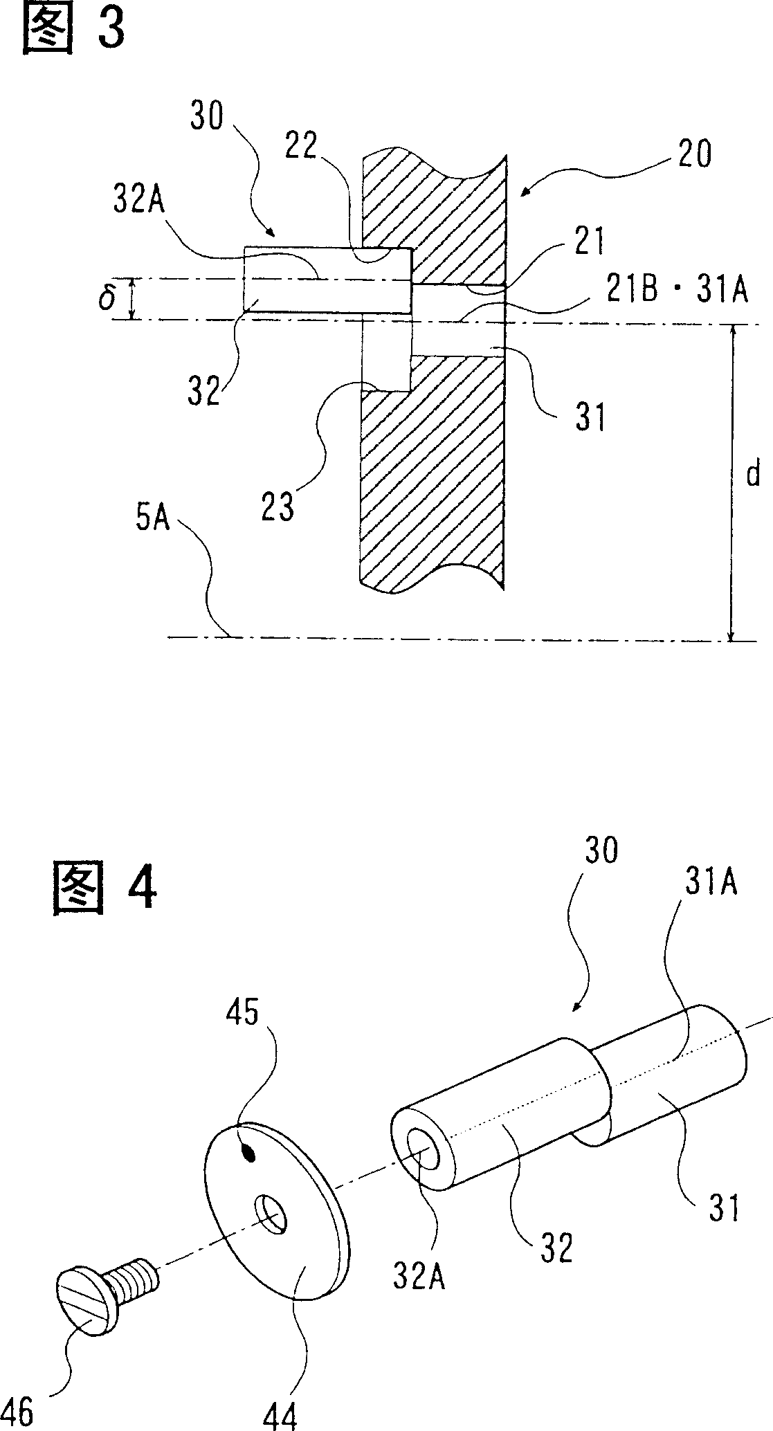
[0047] A mounting hole 21 for fitting the shaft por...


PUM


Abstract

This invention provides a needle-bar stroke adjustment device capable of reducing a machining cost rise. The needle-bar stroke adjustment device 1 includes a crank 20 and an eccentric pin 30. The crank 20 is secured to an arm shaft 5 which is driven for rotation. The eccentric pin 30 includes axially parallel and eccentric shanks 31 and 31 at both ends. The crank 20 is provided with a mounting hole 21 and two counter sunk holes 22 and 23. One of the shanks 31 of the eccentric pin 30 can fit into the mounting hole 21. The counter sunk holes 22 and 23 continue with the mounting hole 21. The two counter sunk holes 22 and 23 are formed in symmetry with respect to the horizontal axis 21C of the mounting hole 21 and communicate with each other. The other of the shanks 32 of the eccentric pin 30 can fit into the counter sunk holes 22 and 23.

Description

technical field [0001] The invention relates to a needle bar stroke adjustment device for adjusting the amount of up and down strokes of a needle bar of a sewing machine. Background technique [0002] Since the material to be sewn by the sewing machine can be processed in a wide range of thickness from thick material to thin material depending on the application, it is necessary to use the same needle bar up and down strokes for all the materials. very difficult. Therefore, conventionally, the amount of the up and down stroke of the needle bar is adjusted according to the thickness of the cloth. [0003] As everyone knows, there is a device using an eccentric pin to adjust the amount of the up and down stroke of the needle bar. [0004] For example, the device described in Japanese Patent Publication No. Hei 11-226283 has a structure that one end of the connecting rod is supported on the needle bar, and the other end of the connecting rod is rotatably installed on the cran...

Claims


Application Information

Patent Timeline
IPC IPC(8): D05B55/14
Inventor 小山幸二
Owner JUKI CORP
Why Eureka
Try Eureka