
Steel bar automatic feeding device

A technology for automatic feeding and bar material, which is used in measuring devices, analyzing materials, and testing the strength of materials by applying a stable bending force. It can solve the problems of potential safety hazards, low inspection efficiency, inaccurate inspection results, etc. Accurate, ensure safety, and reduce labor intensity

Active Publication Date: 2007-07-25
ZHUZHOU HARD ALLOY GRP CO LTD
View PDF4 Cites 0 Cited by
  • Summary
  • Abstract
  • Description
  • Claims
  • Application Information

AI Technical Summary

Problems solved by technology

[0002] When the bending strength of bars, especially fine bars, is tested by a material testing machine, since there is no suitable auxiliary feeding mechanism, the efficiency of manual inspection is very low, and a maximum of about 8 pieces can be inspected per minute, and because the placement position is different each time , the inspection results are inaccurate, and it is not suitable for mass inspection, and there are also potential safety hazards

Method used


Image

  • Steel bar automatic feeding device
  • Steel bar automatic feeding device
  • Steel bar automatic feeding device

Examples


Embodiment Construction

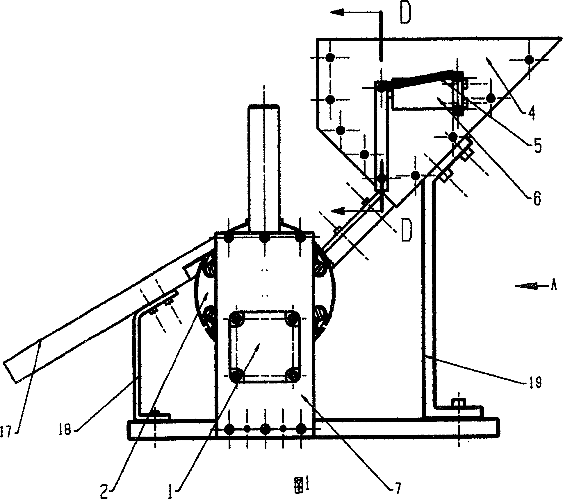
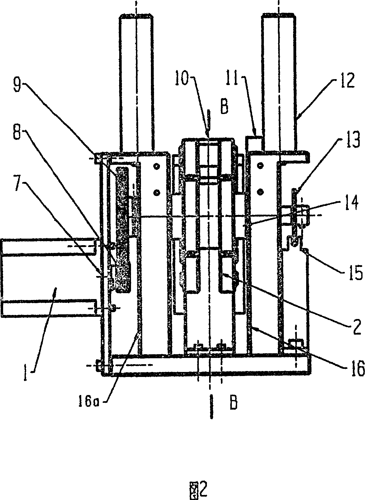
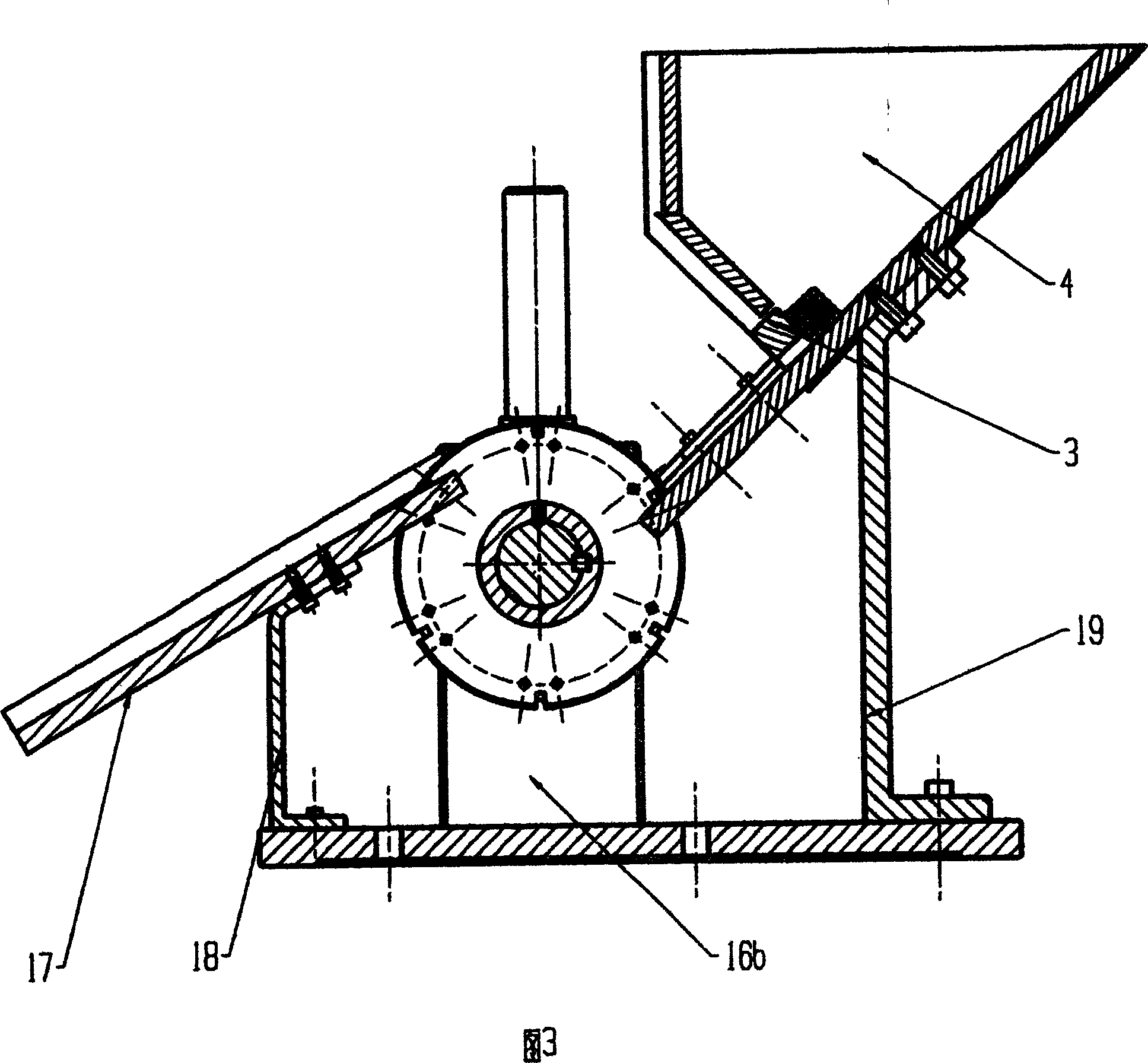
[0011] The bar material automatic feeding device of the present invention is made up of mechanical parts, pneumatic material shifting parts and electric control part; As shown in Figure 1-Fig. Outlet 17 is supported on rear support 19 and front support 18 on the frame 16; stepper motor 1 is fixed on the support plate 7, and its output end faces the inside of frame 16 and gear 8 is installed, and shaft 14 passes through left and right supports 16a , 16b and fixed on it, the gear 9 is fixed on the shaft 14, close to the outer end of the left bracket 16a and meshed with the gear 8, the feeding turntable 2, the station disk 13 and the gear 9 are coaxially arranged, and the station disk 13 is fixed on On the shaft 14, near the outer end of the right support 16b; on the left support 16a or the right support 16b, a photoelectric sensor 11 that receives the rotation information of the feeding turntable 2 is designed, and a photoelectric sensor 11 that receives the rotation information ...


PUM


Abstract

The invention provides a bar stock automatic feeding device which comprises mechanical transmit part including pack house, framework, discharge hole, fore-and-aft frame, stepping motor, gear set, gear shaft, loading turntable conveyor with spout, coaxial survey posit plate, two photoelectric sensors and positing column connected with external device; pneumatic master part including cylinder, deflector rod and restoring spring; and electric control component whose position detecting circuit connected with gauge control circuit, stepping motor-dive, stepping motor and turntable position control circuit, with information inputting test being output the computer while react to positing measuring circuit; and speed control circuit being connected with gauge control circuit, air value control circuit and magnetic value; computer output information of testing output reacting to position detecting circuit and gauge control circuit.

Description

technical field [0001] The invention relates to an automatic feeding device for solid raw materials, in particular to an automatic feeding device for rods. Background technique [0002] When the bending strength of bars, especially fine bars, is tested by a material testing machine, since there is no suitable auxiliary feeding mechanism, the efficiency of manual inspection is very low, and a maximum of about 8 pieces can be inspected per minute, and because the placement position is different each time , the inspection results are inaccurate, and it is not suitable for mass inspection, and there are also potential safety hazards. Contents of the invention [0003] In view of the above problems, the present invention provides an automatic feeding device with accurate positioning, high efficiency, safety and adaptability to bars. [0004] The bar material automatic feeding device of the present invention is composed of a mechanical transmission part, a pneumatic shifting pa...

Claims


Application Information

Patent Timeline
Patent Type & Authority Patents(China)
IPC IPC(8): G01N3/02G01N3/20
Inventor 蒋飞岳江山陈光明
Owner ZHUZHOU HARD ALLOY GRP CO LTD
Learn More