Un-disassembled expandable type plate-connecting structure
A connection structure, disassembly-free technology, applied in the direction of connection components, furniture connection, mechanical equipment, etc., to achieve the effect of good interchangeability, wide range of uses, and convenient operation
- Summary
- Abstract
- Description
- Claims
- Application Information
AI Technical Summary
Problems solved by technology
Method used
Image
Examples
Embodiment 1
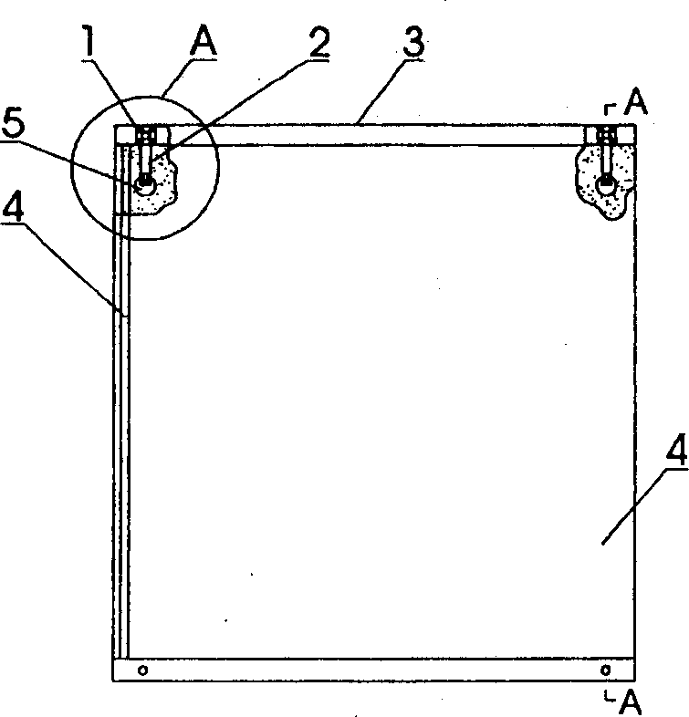
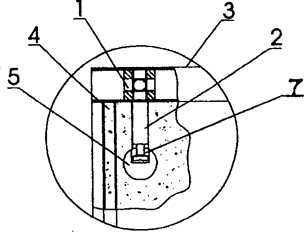
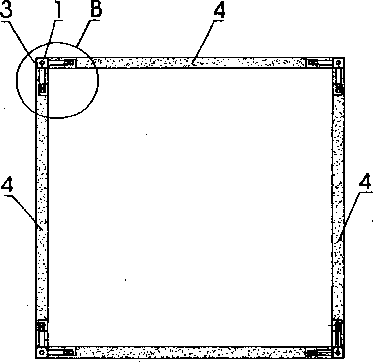
[0020] see Figure 1-Figure 6 As shown, the connection assembly structure of the present invention and its connection structure with the connected plate are as follows: the connection assembly 9 is composed of a square tube 3 , a square nut 1 , and a connection screw 2 . The centers of the six faces of the square nut 1 are tapped with screw holes, and the centerlines of the six screw holes intersect at the center point of the square nut 1 . In the square tube 3, two or more than two square nuts 1 are housed in a sliding fit mode. After determining the position of each square nut 1 in the square tube 3, the corresponding bolts of each square nut 1 on the square tube 3 faces are arranged. The holes are drilled with through holes. One end of the connecting screw 2 is provided with a thread, and the other end is provided with a concave ring groove 7, and the threaded ends of the connecting screw 2 are respectively screwed into the screw holes of the corresponding square nut 1, an...
Embodiment 2
[0023] see Figure 7 , Figure 8 Shown, the connection structure of a unit cabinet of the present invention is such: at first 4 pieces of square connected plates 4 that need to be connected into the cabinet are drilled with deep holes perpendicular to the plate limit on the edge of the connected plate, and in the deep hole There is a blind hole perpendicular to the deep hole at the bottom, which is used to inlay the turnbuckle 5, and then insert the relevant connecting screw rods 2 of the four connecting components 9 into the corresponding deep holes in the four connected plates 4, and each When the turnbuckle 5 is tightened, it becomes a unit cabinet frame. If make the unit cabinet, then install the backboard 10 behind the cabinet frame. If the cabinet door is installed in the front, it becomes a unit cabinet.
Embodiment 3
[0025] see Figure 9 , Figure 10 As shown, these two accompanying drawings show a specific example of a combined cabinet or frame that is expanded from a single unit cabinet or frame into various arrangement designs. First, drill a deep hole on the connected plate 4 that needs to be expanded and inlay the turnbuckle 5, screw the connecting screw 2 on the connecting component 9 in the expansion direction, then insert the corresponding connected plate 4 into the connecting screw 2, and tighten the screw. Buckle 5, so that it can be lapped into various styles of cabinets, such as Bogu racks, wine racks, etc., if the backboard is installed, it will become various styles of cabinets, such as bookcases, audio-visual cabinets, ladder cabinets, Display cabinets, etc., such as reinstalling cabinet doors, become combination cabinets of various styles.
PUM
 Abstract
Description
Claims
Application Information
 - R&D
- Intellectual Property
- Life Sciences
- Materials
- Tech Scout
- Unparalleled Data Quality
- Higher Quality Content
- 60% Fewer Hallucinations
Browse by: Latest US Patents, China's latest patents, Technical Efficacy Thesaurus, Application Domain, Technology Topic, Popular Technical Reports.
© 2025 PatSnap. All rights reserved.Legal|Privacy policy|Modern Slavery Act Transparency Statement|Sitemap|About US| Contact US: help@patsnap.com


