Marking of an anodized layer of an aluminium object

An anodizing and marking technology, which is applied in the direction of copying/marking method, thin material processing, temperature recording method, etc., can solve the problem of preventing the coloring of the anodized layer

Inactive Publication Date: 2002-02-20
KONINKLIJKE PHILIPS ELECTRONICS NV
View PDF4 Cites 30 Cited by
  • Summary
  • Abstract
  • Description
  • Claims
  • Application Information

AI Technical Summary

Problems solved by technology

The problem here is that in many cases it is necessary to provide surfaces with, for example, alphanumeric symbols, emblems, operating instructions, or decorative lines, patterns or other structural markings
Although the remaining conversion layer forms a protective layer and prevents the part of the anodized layer adjacent to the formed marking from breaking, this method of marking the anodized layer has the disadvantage that the marking forms an anodized layer thickness Actually reduced by 25-70 (μm), this disadvantage is not conducive to the use of the layer as a sliding layer such as an electric iron
The disadvantage of this method is that a special treatment is necessary to add a contrast-bleaching substance under the influence of laser radiation, and the necessity of adding a contrast-bleaching substance under the influence of laser radiation prevents the coloring of the anodized layer

Method used


Image

  • Marking of an anodized layer of an aluminium object
  • Marking of an anodized layer of an aluminium object
  • Marking of an anodized layer of an aluminium object

Examples


Embodiment Construction

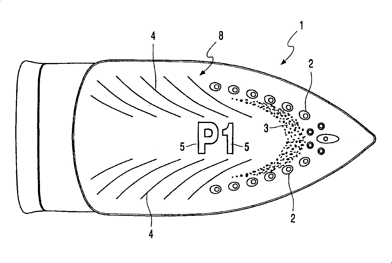
[0015] The part shown in the example figure is the bottom 1 of a steam iron with an outlet 2 for the passage of steam and markings such as: dots of the area 3, lines 4, and numeral-symbol characters 5 like typefaces .

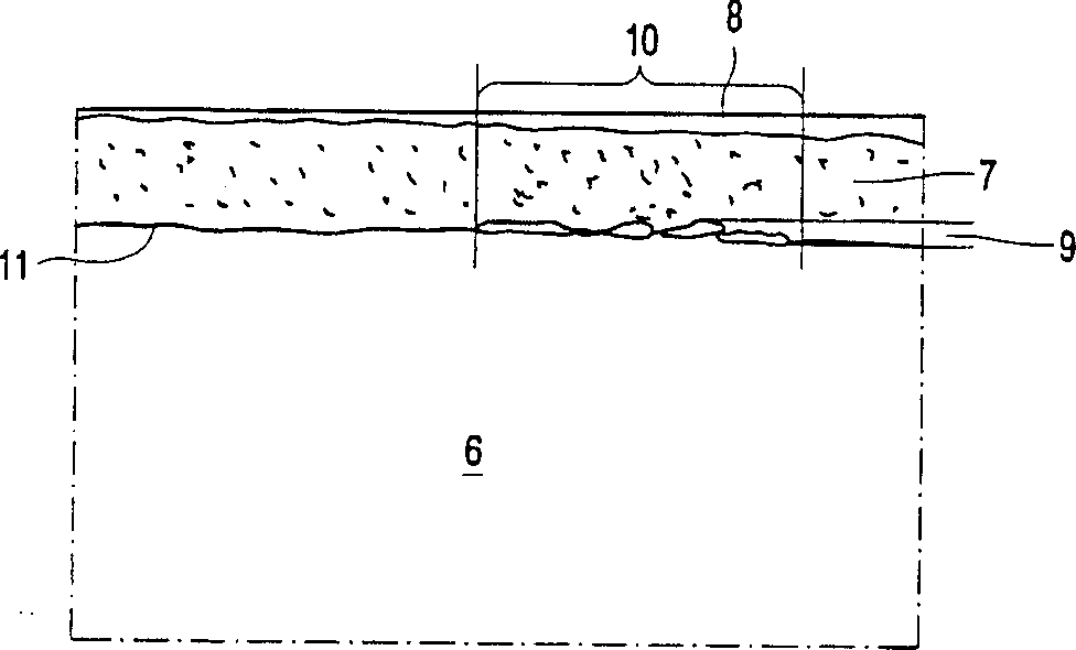
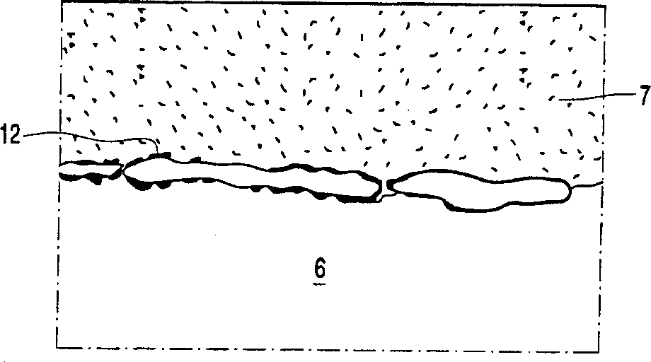
[0016] The bottom 1 is composed of a substantially plate-shaped substrate 6 made of aluminum alloy and an anodized outer layer 7 forming an ironing surface 8 of the bottom 1 . this is in Figure 2 to Figure 4 , which are micrographs at magnifications of 625X, 2500X and 10,000X, respectively.

[0017] The area of ​​surface 8 forming indicia 3 to 5 can be visually distinguished by the human eye from other parts of surface 8 because it has visual properties that differ from corresponding visual properties of adjacent and other parts of surface 8 . The different visual properties of the regions of the surface 8 forming the markings 3 to 5 in this example are the chromaticity and gloss of these regions. These areas are gray-black to black in shade and somewhat le...


PUM

PropertyMeasurementUnit
wavelengthaaaaaaaaaa

Abstract

A marking (3 to 5) is provided in a surface (8) of an element (1) which comprises a substrate (6) of aluminum or an alloy thereof and an anodized outer layer (7) in that a region (10) of the surface (8) is irradiated with a laser beam such that at least one visual property of the surface (8) in said region (10) is changed and a visual marking (3 to 5) is obtained which is observable to the human eye. The laser beam penetrates the anodized outer layer (7) at least to a major degree and induces the change in the at least one visual property substantially locally only in a zone (9) where the anodized outer layer (7) adjoins the substrate (6).

Description

technical field [0001] The invention relates to a method for marking the surface of a component comprising a substrate as defined in the preamble of claim 1 having an anodized outer layer of aluminum or an alloy thereof. The invention also relates to a component as defined by the preamble of claim 9 having an anodized surface. Background technique [0002] The protective layer of aluminum products obtained by anodizing usually has high hardness, high wear resistance, good adhesion to the substrate, and good heat resistance. This makes anodized surfaces ideal for use as surface protection for items that come into strong contact with other surfaces, such as irons, razors, door handles, buttons, etc. The problem here is that in many cases it is necessary to provide surfaces with eg alphanumeric symbols, emblems, operating instructions, or decorative lines, patterns or other structural markings. In this case, it is important that the mark at least in the above items has subs...

Claims


Application Information

Patent Timeline
Patent Type & Authority Applications(China)
IPC IPC(8): B23K26/00B23K103/10B41M5/26B44B7/00B44C1/00B44C1/22C23C26/02C25D11/18
CPCC25D11/18B44C1/228B44B7/002B44C1/005B41M5/262C23C26/02Y10T428/24802
Inventor K·K·耶奥
Owner KONINKLIJKE PHILIPS ELECTRONICS NV
Why Eureka
Try Eureka