Method for cutting sheet-metal plates into sheet-method strips and a cutting device for carrying out the same

A technology of metal plates and metal strips, which is applied in the field of devices for transporting metal strips and devices for shearing metal plates, which can solve the problems of increased space requirements, stable metal plates, and expensive positioning beds

Inactive Publication Date: 2002-03-20
ELPATRONIC AG
View PDF1 Cites 8 Cited by
  • Summary
  • Abstract
  • Description
  • Claims
  • Application Information

AI Technical Summary

Problems solved by technology

The provision of sheet metal stabilization and positioning beds is expensive and significantly increases the space requirement of the device (Abstapler) / disc shear unit for removing the sheets from the stack

Method used


Image

  • Method for cutting sheet-metal plates into sheet-method strips and a cutting device for carrying out the same
  • Method for cutting sheet-metal plates into sheet-method strips and a cutting device for carrying out the same
  • Method for cutting sheet-metal plates into sheet-method strips and a cutting device for carrying out the same

Examples


Embodiment Construction

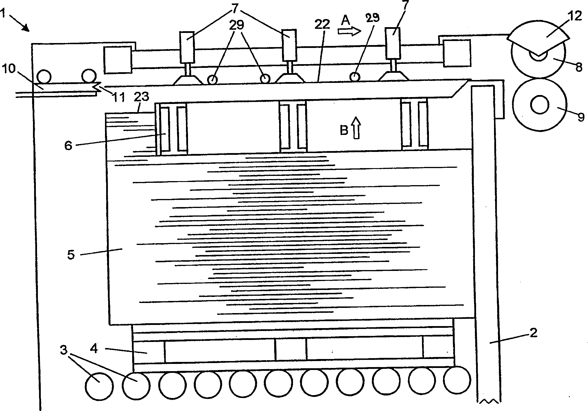
[0026] figure 1 A side view of a shearing device 1 is shown, with parts of the frame 2 omitted in order to show the shearing device more clearly. The device has a receiving device 3 on which a sheet metal stack 5 is received in the device 1 , the sheet metal stack 5 resting on a base plate 4 . Here, the sheet metal stack can be clamped by side guides and expansion magnets 6 in the area where the sheet metal is removed from the stack. Above the stack are several means 7 for removing metal sheets from the stack, which are able to release and lift the uppermost sheet metal in the stack from the stack, for example by means of the illustrated pneumatic suction cups. Such removal of metal sheets from a stack is well known and therefore will not be further described here. figure 1 Also shown in is a shearing unit 12, which in the shown case consists of a disc shear with a plurality of circular blade pairs 8 and 9. Such disc shears are also known and need not be described in detail...


PUM


Abstract

The invention relates to a cutting device for cutting stacked sheet-metal plates into sheet-metal strips using a cutting unit (12). Holding and positioning means (25 to 29 and 13 to 16) are arranged above said stack. This makes a space-saving arrangement possible while maintaining a high degree of cutting precision. The cut sheet-metal strips are fed to another cutting unit by collectively feeding all strips up to a separating point. This simplifies the feeding device and the adaptation thereof to different sheet-metal thickness.

Description

technical field [0001] The invention relates to a method for cutting metal sheets into metal strips according to the preamble of claim 1 . The invention relates to a device for shearing metal sheets according to the preamble of claim 5 . Furthermore, the invention also relates to a method for conveying metal strips according to the preamble of claim 10 and a device for conveying metal strips according to the preamble of claim 13 . Background technique [0002] It is known to cut metal sheets into strips by means of a shearing device, in particular by means of a disc shear. If the two shearing devices are arranged as crank lever shears (winkelschere), the strips cut out of the sheet metal in the first step are fed directly to the second shearer, which is also cut, for example, with a disc shear. The metal strip in the first step is cut into many metal segments respectively. When exact cut positions and high cutting precision are required for metal segments, especially in p...

Claims


Application Information

Patent Timeline
Patent Type & Authority Applications(China)
IPC IPC(8): B21D43/28B23D19/06B23D33/02B65H3/08B65H5/00B65H5/02B65H9/00B65H9/10B65H35/02
CPCB65H2301/44332B65H2406/30B65H9/103B65H3/0816B21D43/28B23D19/06B65H35/02B22D11/126
Inventor P·泰尔纳W·菲雷蒂
Owner ELPATRONIC AG
Why Eureka
Try Eureka