Photomagnetic double-eye myopia physiotherapeutic apparatus

A technique of binocular and myopia, applied in magnetic therapy, physical therapy, ophthalmology treatment, etc., can solve the problem of long time, and achieve the effect of improving vision, simple structure and improving adjustment ability.

Inactive Publication Date: 2002-04-17
BEIJING STAR WANYOU TECH
View PDF1 Cites 4 Cited by
  • Summary
  • Abstract
  • Description
  • Claims
  • Application Information

AI Technical Summary

Problems solved by technology

Therefore, after one eye is treated, the other eye needs to be treated, which takes longer

Method used


Image

  • Photomagnetic double-eye myopia physiotherapeutic apparatus
  • Photomagnetic double-eye myopia physiotherapeutic apparatus
  • Photomagnetic double-eye myopia physiotherapeutic apparatus

Examples


Embodiment Construction

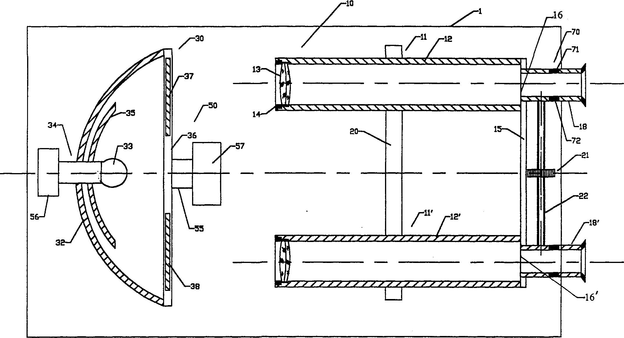
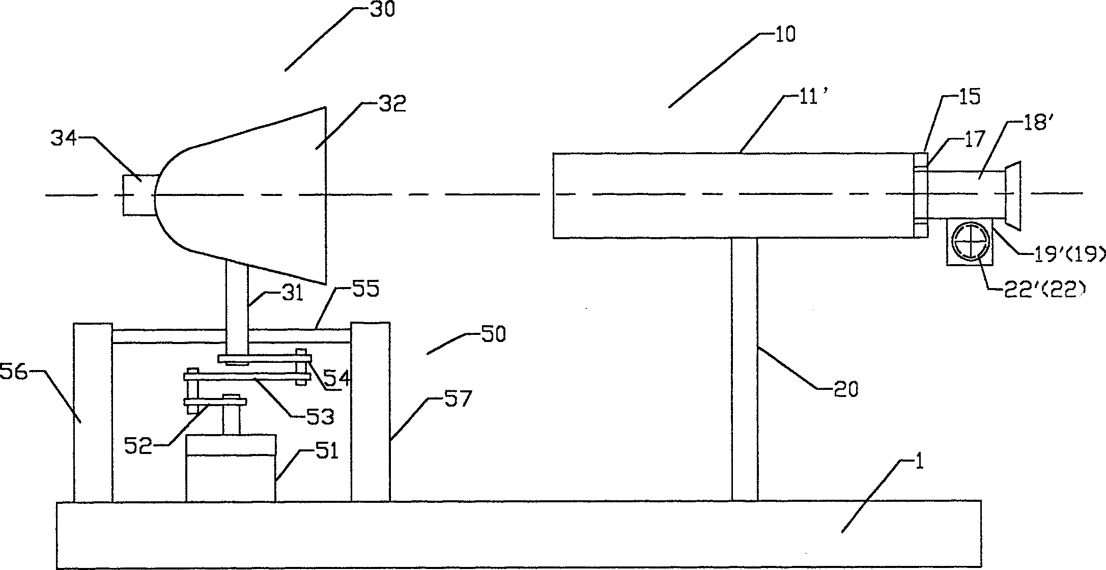
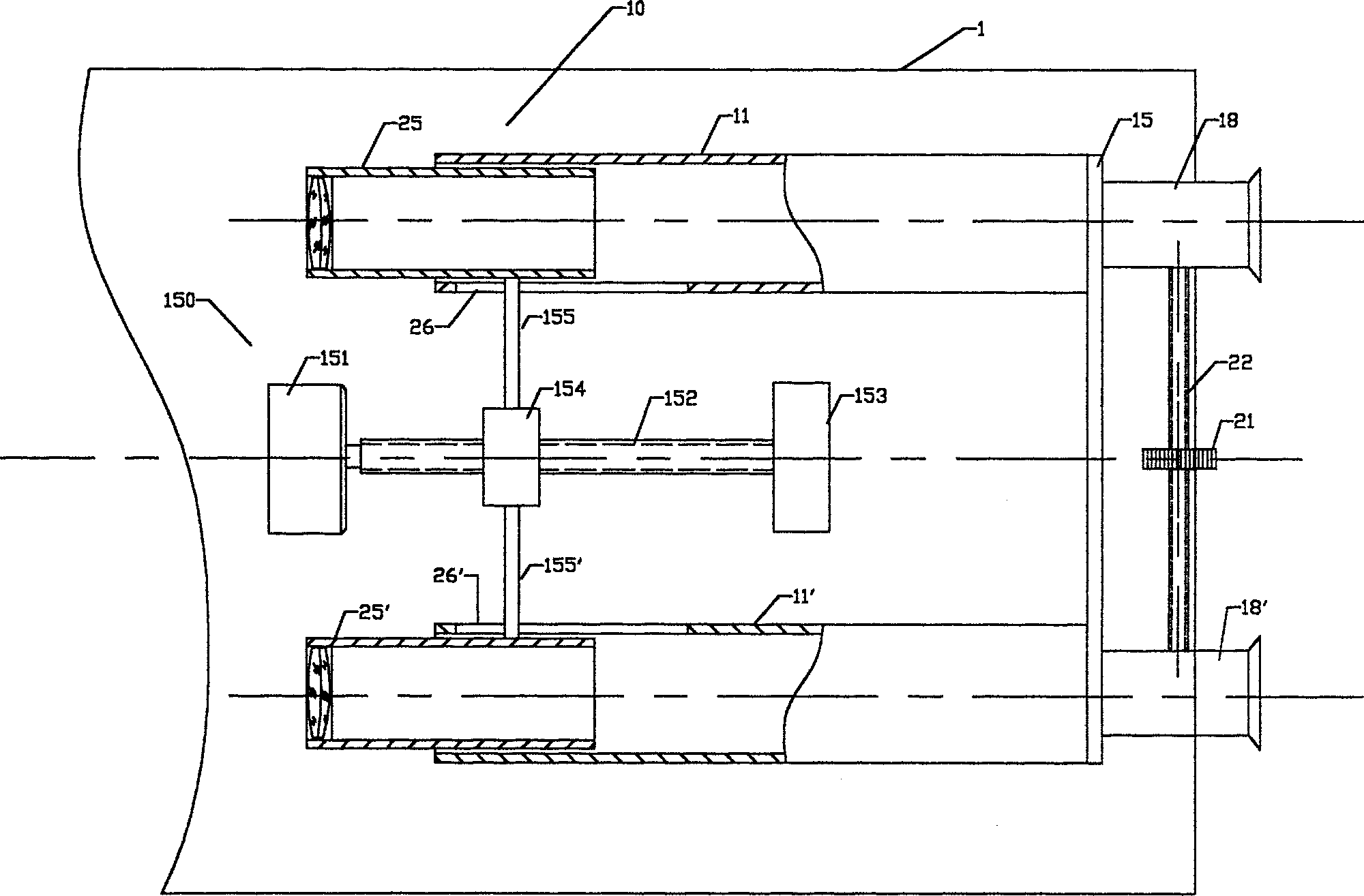
[0021] First refer to figure 1 with figure 2 , shown in the figure is a top view and a front view of an embodiment of the binocular photomagnetic myopia physiotherapy device according to the present invention. The device comprises a binocular visual observation device 10 that is installed on the base 1 and is composed of two identical observation tubes 11 and 11' whose optical axes are parallel to each other. One is positioned at the front of the binocular visual observation device, and The image device 30 whose central axis is consistent with the longitudinal axis of the binocular optical observation device 10, a control device that controls the image device 30 to move back and forth between the near point and the far point of the observer's eyes along the longitudinal axis of the binocular visual observation device 10 50, and the magnetic therapy device 70 installed in the observation hole tubes of the observation tubes 11 and 11'.

[0022] The binocular visual observatio...


PUM


Abstract

The photomagnetic myopia physiotherapeutic apparatus of the present invention includes one binocular viewing observer device, one image device in front of the observer device, one controller to make the image produced by the image device generate the visual effect from the near to the distant, or vice versa, and one magnetotherapeutic device inside the observer device. The apparatus is simple in structure, easy to use and interesting to treated children.

Description

technical field [0001] The invention relates to an eye myopia physical therapy device, in particular to a binocular photomagnetic myopia physical therapy device. Background technique [0002] Eye refractive errors, especially the number of young people with myopia, have become a very serious problem. Many experts and people of insight in the field of ophthalmology have proposed various solutions for the treatment of juvenile myopia, including various solutions of drugs and physical therapy. Among them, the Chinese patent application 92101546.1 submitted by the applicant on March 13, 1992 discloses an electromagnetic light myopia physiotherapy device. During physical therapy, the treated eye gazes at images from near to far, and then from far to near through the observation tube of the device, forcing the treated eye to focus continuously, so that the ciliary muscle can be exercised repeatedly and naturally oppressed by the observation ring. The eyeball can change the shape...

Claims


Application Information

Patent Timeline
Patent Type & Authority Applications(China)
IPC IPC(8): A61H5/00A61N2/00
CPCA61H5/00A61N2/002
Inventor 苏洪泉
Owner BEIJING STAR WANYOU TECH
Why Eureka
Try Eureka