Sewing machine

A sewing machine and needle technology, applied in the field of sewing machines, can solve problems such as the excessively long end of the upper thread, and achieve the effects of good operability and cost reduction

Inactive Publication Date: 2002-05-22
JUKI CORP
View PDF1 Cites 6 Cited by
  • Summary
  • Abstract
  • Description
  • Claims
  • Application Information

AI Technical Summary

Problems solved by technology

Since there is no record of this problem in conventional sewing machines, there will inevitably be a problem that the end of the upper thread is too long.

Method used


Image

  • Sewing machine
  • Sewing machine
  • Sewing machine

Examples


Embodiment 1

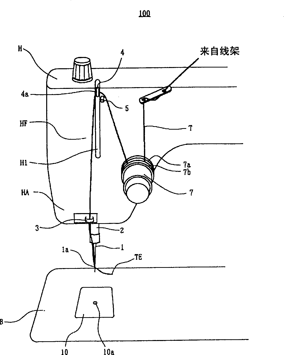
[0039] Such as figure 1 As shown, the sewing machine 100 of the present invention has a machine table B on which clothes are sewn, and a sewing machine head H facing the machine table B and arranged above the machine table, and has the following structure.

[0040] The needle 1 is fixed on the needle bar 2 which moves up and down. The needle bar 2 is linked with the upper shaft (not shown) of the sewing machine arranged on the sewing machine head H, and there is a needle thread T under the needle 1. The pinhole 1a. The thread loop 3 provided on the jaw portion HA protruding downward from the sewing machine head H guides the upper thread T to the needle 1 .

[0041] On the front HF of the sewing machine head H, there are formed on the top of the wire loop 3 and figure 1 Vertical slot H1 on the right. The thread take-up lever 4 has its front end protruding from the long hole H1 to the outside of the sewing machine head H, and is linked with the upper shaft of the sewing machi...

Embodiment 2

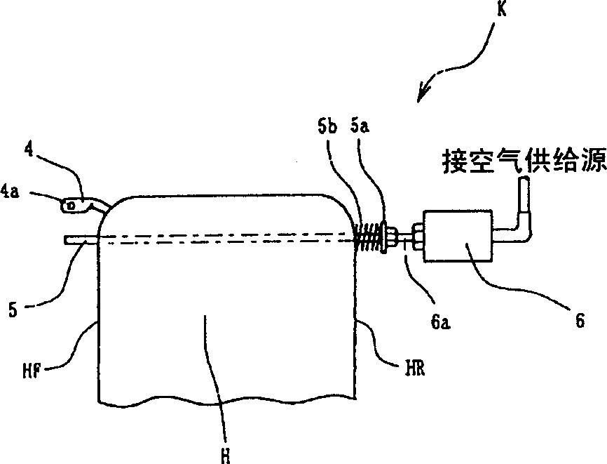
[0072] refer to Image 6 Example 2 will be described. Embodiment 2 is only different in the setting position of the line-reliance stop mechanism K, and the other structures are the same as Embodiment 1. The specific structure is as Image 6 As shown, the thread leaning stop lever 5 is arranged on the side of the needle opposite to the thread stand relative to the long groove H1, and is located approximately near the center of the long groove H1 in the vertical direction.

[0073] The setting position of the line stop lever 5, such as Image 6 As shown, when the hook tip 11a of the thread shuttle 11 is hung on the thread loop L, the thread take-up lever 4 is located at a slightly lower position in the vertical direction, and at the same time, when the thread leaning stop lever 5 is in the entry state, its front end is located at Entry position directly below the upper thread T hanging on the thread take-up lever 4.

[0074] In this way, according to this structure, after th...


PUM


Abstract

A sewing machine, where is disposed a securing pin 5 on the front surface HF of a sewing machine H so as to be able to project therefrom and, before a sewing needle 1 is moved to its bottom dead point after a thread is cut, the securing pin 5 is projected to thereby secure an upper thread T provided on a thread take-up 4. Also, even in case where the operation of the sewing machine is started, the projecting state of the securing pin 5 is held. That is, when the thread take-up 4 is moved down once and, after then, the thread take-up 4 is moved up; and, when the upward moving thread take-up 4 reaches its top dead point, the securing pin 5 is retreated. The sewing machine can draw out an end of an upper thread to the rear side of cloth, limiting the amount of the upper thread drawn out at a first stitch by means of a simple construction, and to prevent the upper thread from being pulled out when the cloth is taken out by limiting the amount of the upper thread drawn out when a sewing needle stops at an upper dead point after the thread is cut off.

Description

technical field [0001] The present invention relates to a sewing machine which limits the feeding amount of upper thread. Background technique [0002] In the past, from the viewpoint of emphasizing the aesthetics of the sewn product, when the first stitch was formed by limiting the feeding amount of the upper thread, the sewing machine that pulled the end of the upper thread protruding from the surface side of the cloth to the back side of the cloth, For example, it is disclosed in JP-A-62-186892. [0003] That is, in the above-mentioned sewing machine, there is a thread clamp mechanism that clamps the upper thread between the thread take-up lever and the machine needle and is arranged below the thread take-up lever. , to stop supplying the upper thread to the needle, so after that, the end of the upper thread extended from the needle is pulled downward through the sewing product and the hole of the needle plate due to the rotation of the thread hook to pull out the thread...

Claims


Application Information

Patent Timeline
Patent Type & Authority Applications(China)
IPC IPC(8): D05B53/00D05B47/00D05B51/00D05B65/06
CPCD05B47/04D05B51/00D05B53/00D05B63/02D05B65/06
Inventor 门胁真次郎
Owner JUKI CORP
Why Eureka
Try Eureka