Radiator mounting structure in vehicles

A radiator and vehicle technology, which is applied to the arrangement of vehicle components, power unit cooling combination, motorcycles, etc., can solve the problems of small degree of freedom of conduit piping, prolonged water injection time, time-consuming, etc., and achieves compact cooling water circulation circuit , Improve water injection performance and avoid the effect of increasing costs

Inactive Publication Date: 2002-05-22
HONDA MOTOR CO LTD
View PDF0 Cites 6 Cited by
  • Summary
  • Abstract
  • Description
  • Claims
  • Application Information

AI Technical Summary

Problems solved by technology

[0004] However, in a vehicle in which the engine body is mounted on the body frame so that the axis of the cylinder bore is substantially in the front-rear direction of the body frame, the length of the water cooling jacket provided on the engine body in the vertical direction is reduced, and the duct of the cooling device is vertically aligned. The degree of freedom of the piping direction is small, the water pressure is also low, it takes time to exhaust the air from the cooling device, and the water injection time is also prolonged
[0005] In order to increase the water pressure, it is considered to use a radiator with a special shape in which the water nozzle protrudes upward from the upper box. At the same time, a water nozzle is installed on the box connected to the radiator and configured separately from the radiator. However, This structure results in increased cost

Method used


Image

  • Radiator mounting structure in vehicles
  • Radiator mounting structure in vehicles
  • Radiator mounting structure in vehicles

Examples


Embodiment Construction

[0022] The implementation form of the present invention will be described below according to an embodiment of the present invention shown in the accompanying drawings.

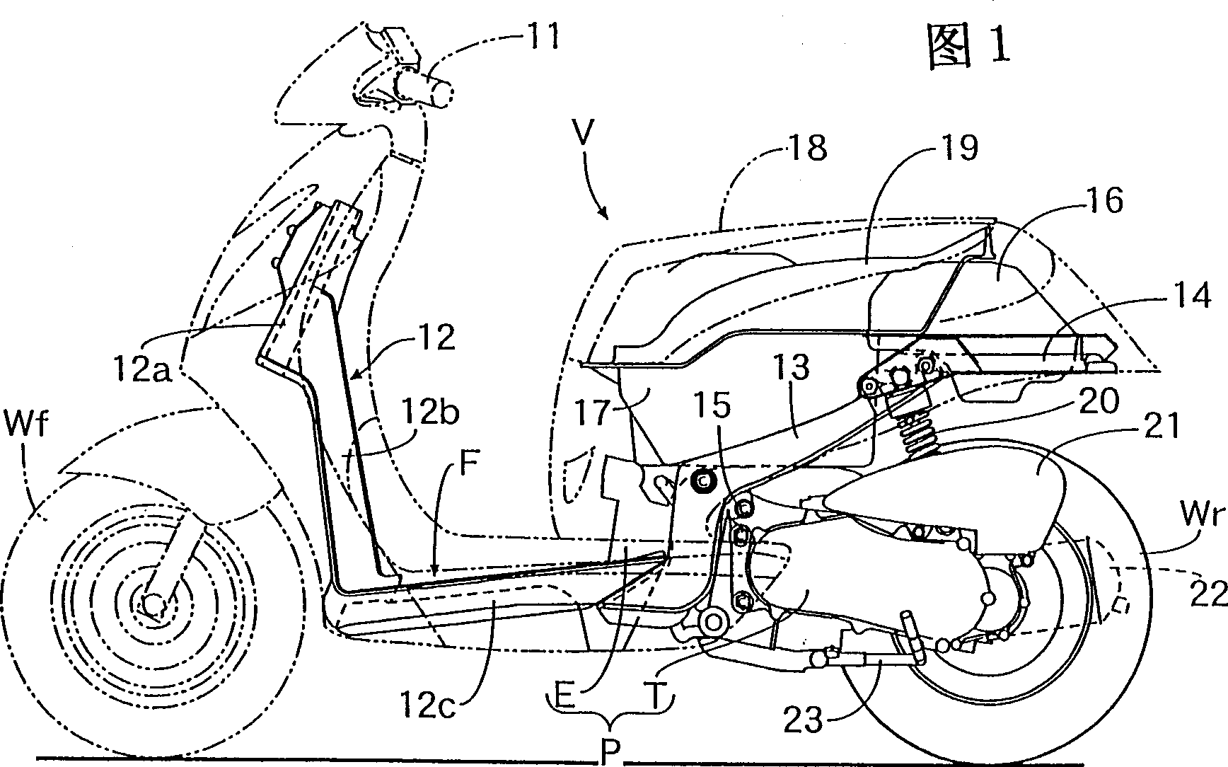
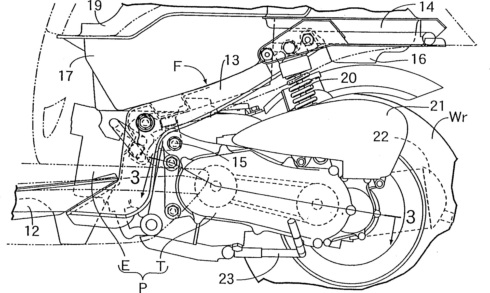
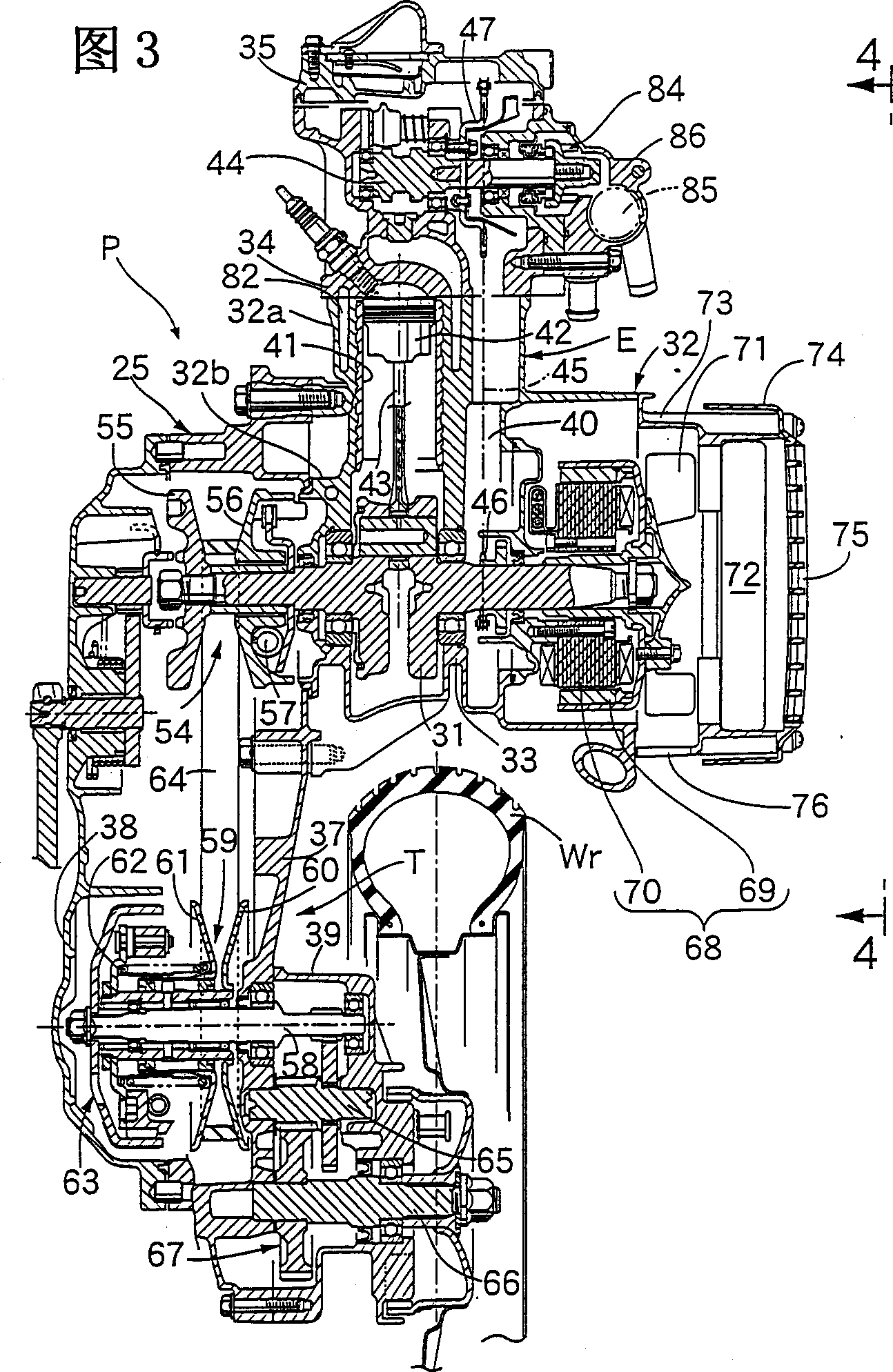
[0023] Figure 1~ Figure 8 Representing an embodiment of the present invention, Fig. 1 is the overall side view of scooter, figure 2 is an enlarged view of the main part of Figure 1, and Figure 3 is along the figure 2 Figure 4 is a side view along line 4-4 of Figure 3, Figure 5 is a side view corresponding to Figure 4 with the radiator cover removed, Figure 6 is a side view along The sectional view of line 6-6 of Fig. 4, Fig. 7 is the 7 direction plan view of Fig. 6, Figure 8 is a perspective view of the radiator and radiator shroud.

[0024] First, in Figure 1 and figure 2 Among them, the body frame F of the scooter V equipped with the front wheel Wf steered by the steering handle 11 and the rear wheel Wr driven by the swing power unit P is divided into a front body frame 12, a middle body frame 13, and ...


PUM


Abstract

In a vehicle in which an engine main body is mounted to a vehicle body frame in an attitude in which an axis line of a cylinder bore is substantially in line with a front and rear direction of the vehicle body frame and a radiator constituting a portion of a cooling apparatus capable of circulating cooling water of a water jacket is attached to the engine main body at a side of the cylinder bore, to promote air bleeding performance and water filling performance in the cooling apparatus while avoiding an increase in cost. Therefor, a water filling cap 88 is attachably and detachably mounted to an upper end of a water filling pipe 87 extended upwardly from one end portion of an upper tank 77 in line with a front and rear direction of a vehicle body frame and a radiator 72 is attached to an engine main body 25 in an attitude of being inclined to a horizontal face such that the water filling cap 88 is disposed at a topmost position in a cooling apparatus 83.

Description

technical field [0001] The present invention relates to a radiator configuration in which an engine main body is mounted on a body frame with the axis of the cylinder bore substantially along the front-rear direction of the body frame, and upper and lower casings and cooling pipes connecting these casings are provided. A part of the cooling device that can circulate the cooling water of the water jacket, and a vehicle that is attached to the engine body at the side of the aforementioned cylinder bore, particularly relates to the improvement of the radiator mounting structure. Background technique [0002] In the prior art, for example, from Japanese Unexamined Patent Application Publication No. 59-78128, there is known a vehicle in which a radiator is mounted on an engine body mounted on a body frame in such a manner that it is disposed on the side of a cylinder bore provided in the engine body. . [0003] In the engine disclosed in the above-mentioned Utility Laid-Open No....

Claims


Application Information

Patent Timeline
IPC IPC(8): B60K11/04B62J99/00B62M7/06F01P3/18F01P11/00
CPCB60K11/04B62M7/06F01P11/0209
Inventor 大城健史
Owner HONDA MOTOR CO LTD
Why Eureka
Try Eureka