Wiring base plate, display device, semiconductor chip and electronic machine

A technology for wiring substrates and display devices, applied to semiconductor devices, semiconductor/solid-state device components, circuit devices, etc., can solve problems such as failure to maintain wiring quality and damage to metal wirings

Inactive Publication Date: 2002-05-22
BOE TECH GRP CO LTD
View PDF0 Cites 4 Cited by
  • Summary
  • Abstract
  • Description
  • Claims
  • Application Information

AI Technical Summary

Problems solved by technology

[0008] As mentioned above, if the wiring pattern formed on the substrate is formed with metals such as APC and Cr, it is very advantageous in reducing the resistance value, but on the other hand, it is known that the metal wiring is damaged due to corrosion and cannot be used. Another Problem with Maintaining Cabling Quality

Method used


Image

  • Wiring base plate, display device, semiconductor chip and electronic machine
  • Wiring base plate, display device, semiconductor chip and electronic machine
  • Wiring base plate, display device, semiconductor chip and electronic machine

Examples


no. 1 Embodiment

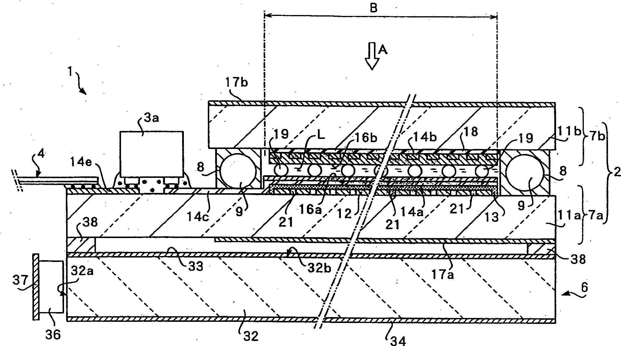
[0056] figure 1 An example in which the wiring board of the present invention is applied to a liquid crystal device, which is an example of a display device, is shown. In addition, when distinguishing liquid crystal devices according to driving methods, there are simple matrix and active matrix driving methods, but figure 1 The illustrated liquid crystal device is a simple matrix liquid crystal device. In addition, when classifying liquid crystal devices according to the method of supplying light, various methods such as reflective type, transmissive type, and transflective type can be considered, but figure 1 The illustrated liquid crystal device is a transflective liquid crystal device.

[0057] The reflective type is a liquid crystal device having a structure in which external light such as sunlight or indoor light is reflected on the back side of the liquid crystal layer, and the reflected light is used as a light source. In addition, the so-called transmissive type ...

no. 2 Embodiment

[0093] Figure 5 show Figure 4 A modified example of the metal wiring shown. related Figure 5 The illustrated plurality of metal wirings 14e is compatible with Figure 4 The illustrated embodiment is the same, that is, different voltages V1 to V4 are applied, and the protective wiring 29 made of conductive oxide, that is, ITO, is interposed between the anode-side metal wiring 14e to which a high voltage is applied and the anode-side metal wiring 14e to which a relatively low voltage is applied. It is arranged between the cathode side metal wirings 14e.

[0094] Figure 5 The present embodiment shown with Figure 4 The illustrated embodiment differs in that the ITO is removed from above the metal wiring 14e. In this way, even when ITO is not laminated on the metal wiring 14e, it is possible to prevent corrosion of the metal wiring on the anode side.

no. 3 Embodiment

[0096] Image 6 show Figure 4 Another modification of the metal wiring shown. related Image 6 The illustrated plurality of metal wirings 14e is compatible with Figure 4 The illustrated embodiment is the same, that is, different voltages V1 to V4 are applied, and the protective wiring 29 made of conductive oxide to ITO is interposed between the anode side metal wiring 14e to which a high voltage is applied and the cathode side to which a relatively low voltage is applied. The metal wirings 14e are arranged between each other, and the same ITO as the protective wiring 29 is laminated and covered on the metal wirings 14e, and the like.

[0097] Image 6 The present embodiment shown with Figure 4 The difference of the illustrated embodiment is that the connection between the protective wiring 29 and the ITO capping layer 41 on the metal wiring 14e is released, and the protective layer 29 is placed in a potential-free state. In this way, even when the protective wiring 29...


PUM


Abstract

In order to prevent the corrosion of metal wirings of a wiring pattern made of a metal material having a low electric resistance. A wiring substrate is formed of a plurality of metal wirings 14e formed on a substrate 7c. A guard wiring 29 fabricated of an electrically conductive oxide such as ITO is interposed between at least a pair of adjacent ones of a plurality of metal wirings 14e. When voltages V1, V2, V3, and V4 applied to the metal wirings 14e are related to be V1>V2 >V3 >V4, a guard wiring 29 is present between a metal wiring 14e functioning as an anode and a metal wiring 14e functioning as a cathode, and the anode metal wiring 14e is prevented from being corroded.

Description

technical field [0001] The present invention relates to a wiring board formed by forming metal wiring on a substrate, a display device constructed using the wiring board, a semiconductor chip applied to the wiring board, and an electronic device using the display device or the wiring board. Background technique [0002] In recent years, display devices such as liquid crystal devices have been widely used in display units of electronic devices such as portable computers, mobile phones, and video cameras. In addition, an EL (Electroluminescence device) which is one of the display devices has also been used as a display unit. In a liquid crystal device, liquid crystal as an electro-optic substance is sandwiched between a pair of electrodes, the orientation of the liquid crystal is controlled by controlling the voltage applied to these electrodes, and the light passing through the liquid crystal is modulated by the orientation control of the liquid crystal. Displays images of t...

Claims


Application Information

Patent Timeline
Patent Type & Authority Applications(China)
IPC IPC(8): H05K3/22G02F1/1345G09F9/00G09F9/30H01L23/12H01L27/32H05K1/02H05K1/03H05K1/09
CPCH05K2201/0761H05K2201/0769H05K1/0306H05K1/0256G02F1/1345H05K2201/09781H05K2201/0326H01L2224/16225H01L2224/32225H01L2224/73204H01L2224/05573H01L2224/05568H01L2224/04026H01L2924/00014H01L2924/00H01L2224/05599H05K3/22
Inventor 有贺泰人矢田部聪远藤甲午原田考人
Owner BOE TECH GRP CO LTD
Why Eureka
Try Eureka