
Rolling process for metal strip and corresponding rolling device

A technology for metal strip and rolling equipment, applied in metal rolling, metal rolling, metal processing equipment and other directions, can solve the problems of stability in deformation zone, slippage, strip breakage, etc.

Inactive Publication Date: 2002-06-12
SMS DEMAG AG
View PDF0 Cites 8 Cited by
  • Summary
  • Abstract
  • Description
  • Claims
  • Application Information

AI Technical Summary

Problems solved by technology

In addition, stability problems with regard to the running of the strip, stability problems in the deformation zone and / or slipping phenomena sometimes arise during the rolling process, which can even lead to strip breakage in extreme cases

Method used


Image

  • Rolling process for metal strip and corresponding rolling device
  • Rolling process for metal strip and corresponding rolling device
  • Rolling process for metal strip and corresponding rolling device

Examples


Embodiment Construction

[0020] Description of preferred embodiments

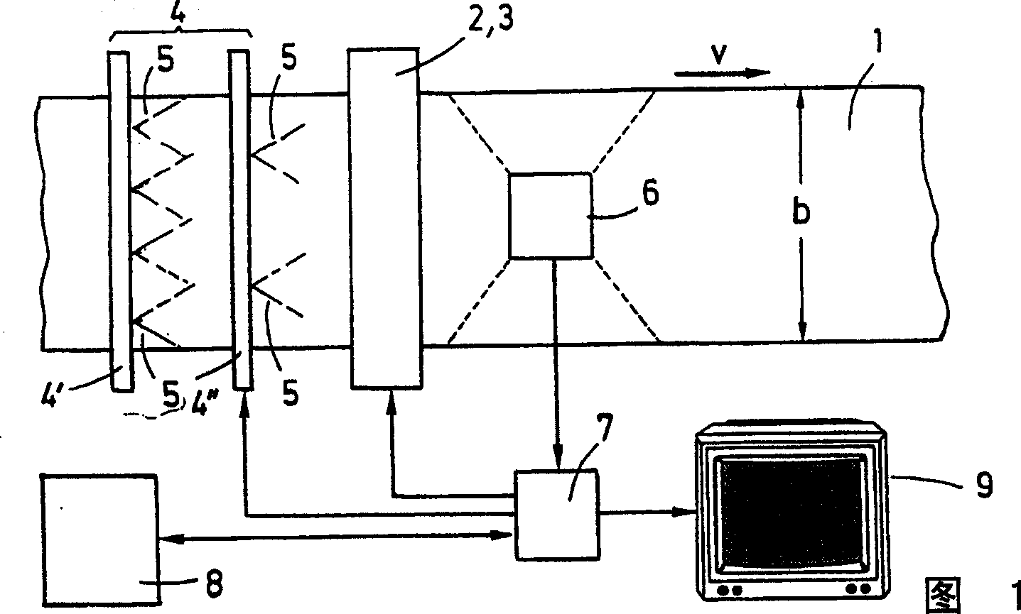
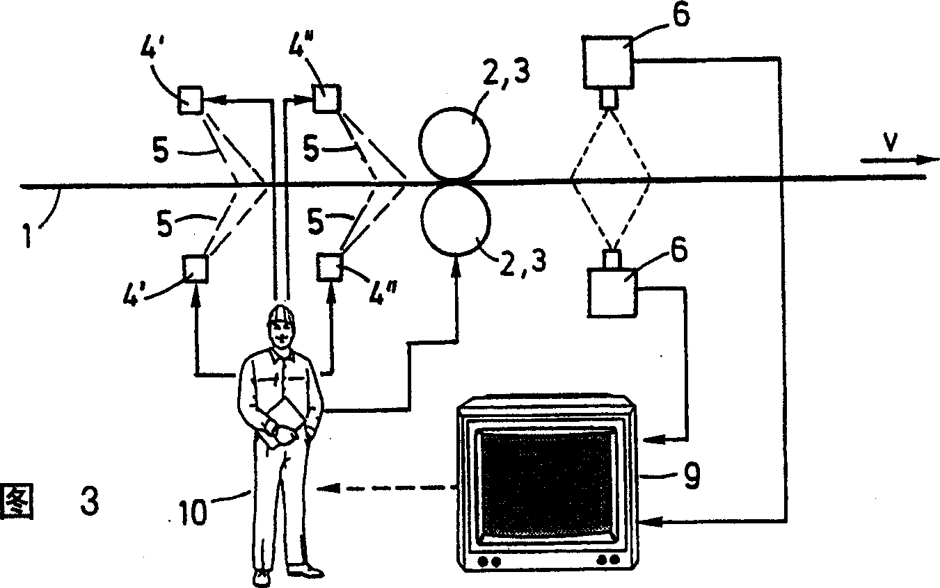
[0021] According to FIG. 1 , a metal strip 1 is rolled at a rolling speed v in a rolling stand 2 with work rolls 3 . According to FIG. 2 , the rolling stand 2 is a two-high rolling stand. That is to say, it only has work rolls 3 . However, the rolling stand 2 can likewise also have backup rolls in one or more rolling planes, optionally also intermediate rolls, pusher systems, etc., or be formed, for example, from a so-called twenty-high stand. The metal strip 1 has a metal band b. According to an embodiment, the metal strip 1 consists of steel. However, it can also consist of another metal, for example copper, aluminum or brass.

[0022] The rolling stand 2 is equipped with a lubrication device 4 . According to FIG. 1 , the lubrication device is arranged in front of the rolling stand 2 . With the aid of this lubricating device 4 , a quantity of lubricant 5 can be applied to the metal strip 1 from both the top and bottom direc...


PUM


Abstract

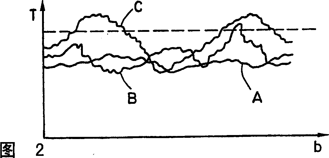
The invention relates to a rolling process for a metal strip (1) having width (b), wherein the metal strip (1) is rolled in at least one rolling stand (2), wherein an amount of lubricant is applied and spread on the width (b) of the metal strip (1), wherein the lubrication process on the width (b) of the metal strip is detected behind the rolling stand (2) and used for regulating the amount and / or distribution of the lubricant (5) and / or at least one rolling parameter (v).

Description

technical field [0001] The invention relates to a rolling method for rolling a metal strip having a metal strip, wherein the metal strip is rolled in at least one rolling stand, wherein a quantity of lubricant is applied over the entire metal strip Dispersion coating onto metal strip, and a corresponding rolling equipment. Rolling methods and rolling equipment of this type are generally known. Background technique [0002] The rolling method developed rapidly here. In order to produce a flat rolled strip, for example, use some back-up rolls, reverse bend the work rolls, move the intermediate rolls, stage cooling and so on. Despite all these measures, the strip produced is not perfectly straight. In addition, stability problems with respect to the running of the strip, stability problems in the deformation zone and / or slipping phenomena sometimes occur during the rolling process, which can even lead to strip breakage in extreme cases. Contents of the invention [0003] ...

Claims


Application Information

Patent Timeline
IPC IPC(8): B21B1/22B21B1/28B21B37/00B21B37/32B21B37/44B21B45/02
CPCB21B37/44B21B1/28B21B45/0251
Inventor H·P·里希特R·霍尔茨
Owner SMS DEMAG AG
Learn More