Device which follows position of sun

A technology of tracking devices and equipment, applied in the direction of solar thermal devices, solar thermal energy, solar ray concentration, etc.

Inactive Publication Date: 2002-06-12
LEONHARD KURZ GMBH & CO KG
View PDF2 Cites 10 Cited by
  • Summary
  • Abstract
  • Description
  • Claims
  • Application Information

AI Technical Summary

Problems solved by technology

However, it is found that the focal point of the hologram lens is too large. In order to install the receiver to receive the radiation concentrated on the focal point of the lens, an auxiliary device needs to be connected between the receiver and the lens.
In addition, this configuration suffers from irregular energy distribution on the receiver surface

Method used


Image

  • Device which follows position of sun
  • Device which follows position of sun
  • Device which follows position of sun

Examples


Embodiment Construction

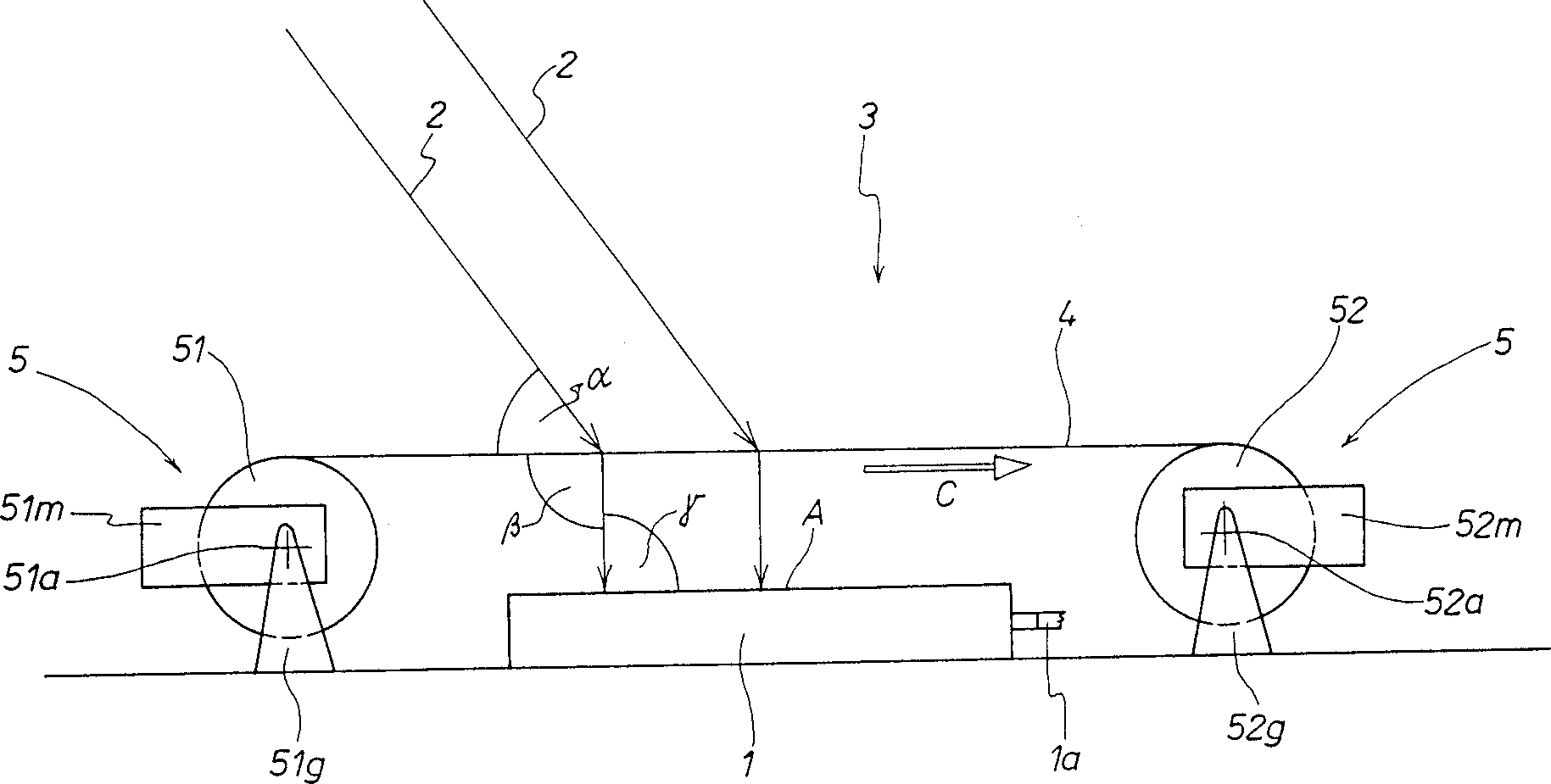
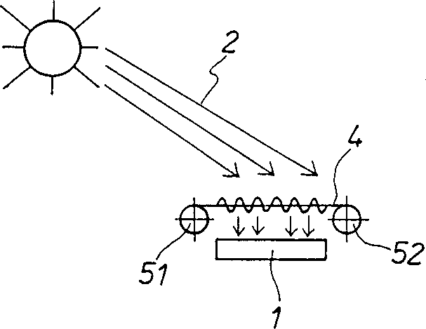
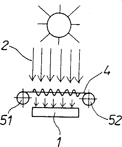
[0033] figure 1 The solar equipment is equipped with a solar unit 1 . The solar unit 1 can be a single solar unit, or a plurality of solar unit cells arranged in a parallel relationship. The solar unit 1 can be in the form of a photovoltaic solar cell, or in the form of a heat-generating solar collector. The sunlight 2 shining on the solar unit 1 is converted into electrical energy or thermal energy by the solar unit 1 . The energy generated is fed by the output 1a of the solar unit 1 to a network (not shown) or to an energy storage device.

[0034] Combined with the solar unit 1 is an optical device 3 through which the sunlight 2 passes. The angle of incidence α of the sunlight depends on the position of the sun. The light hits the surface of the solar unit 1 as vertically as possible.

[0035] The optical device 3 has a diffractive and / or refractive optical body 4 through which sunlight passes, in which case the optical body deflects the sunlight. In the illustrated emb...


PUM


Abstract

The invention relates to a solar installation comprising a solar element and a diffractively and / or refractively functioning optical device via which the incident sunlight is guided onto the solar element in a vertically oriented manner. The optical device is panned by a panning device such that it follows the position of the sun. The optical device uses a light diffracting film which has differently configured sections each comprising a structure the exhibits a different optical effect. The holographic film is moved in relation to the solar element by the operation of the panning device so that consecutive different sections of the film enter an active position above the solar element during panning.

Description

technical field [0001] The present invention relates to optical devices operating in a diffractive and / or refractive manner to pass incident light, preferably sunlight, onto a receiver, preferably a solar unit, the device including controlled tracking means to follow The relative position of the light source to the receiver changes over time, preferably following changes in the position of the sun. Background technique [0002] It is known from practical applications that such optical devices are used in solar energy equipment. This type of equipment is related to the solar unit. In order to maximize the effective use of sunlight, the incident sunlight should be incident on the solar unit in a vertical direction as much as possible. In the practical application of solar energy engineering, the focus system is usually used to achieve this purpose. The focus system uses lenses and hyperboloid mirrors to properly deflect and gather light. To achieve corresponding optimum resu...

Claims


Application Information

Patent Timeline
Patent Type & Authority Applications(China)
IPC IPC(8): G01C1/00F24S23/00F24S23/30F24S50/20G01J1/02G01S3/786G02B5/18G02B5/32G02B26/08G05D3/10H01L31/042H01L31/052
CPCG05D3/105G02B5/1828F24J2/06Y02E10/52F24J2/38Y02E10/44Y02E10/43F21S11/00F24J2/085Y02E10/47F24S23/00F24S50/20F24S23/31
Inventor 沃尔特·库兹
Owner LEONHARD KURZ GMBH & CO KG
Why Eureka
Try Eureka