Multiplex system capable of dividing a group into several subgroup in simple procedure
A multicast address and terminal technology, applied in the field of multicast systems, can solve problems such as complex group address management
- Summary
- Abstract
- Description
- Claims
- Application Information
AI Technical Summary
Problems solved by technology
Method used
Image
Examples
no. 1 example
[0055] see Figures 4 to 9 , the first embodiment of the present invention will now be described.
[0056] Figure 4 The entire structure of a multicast conference system according to the first embodiment of the present invention will be described by way of example.
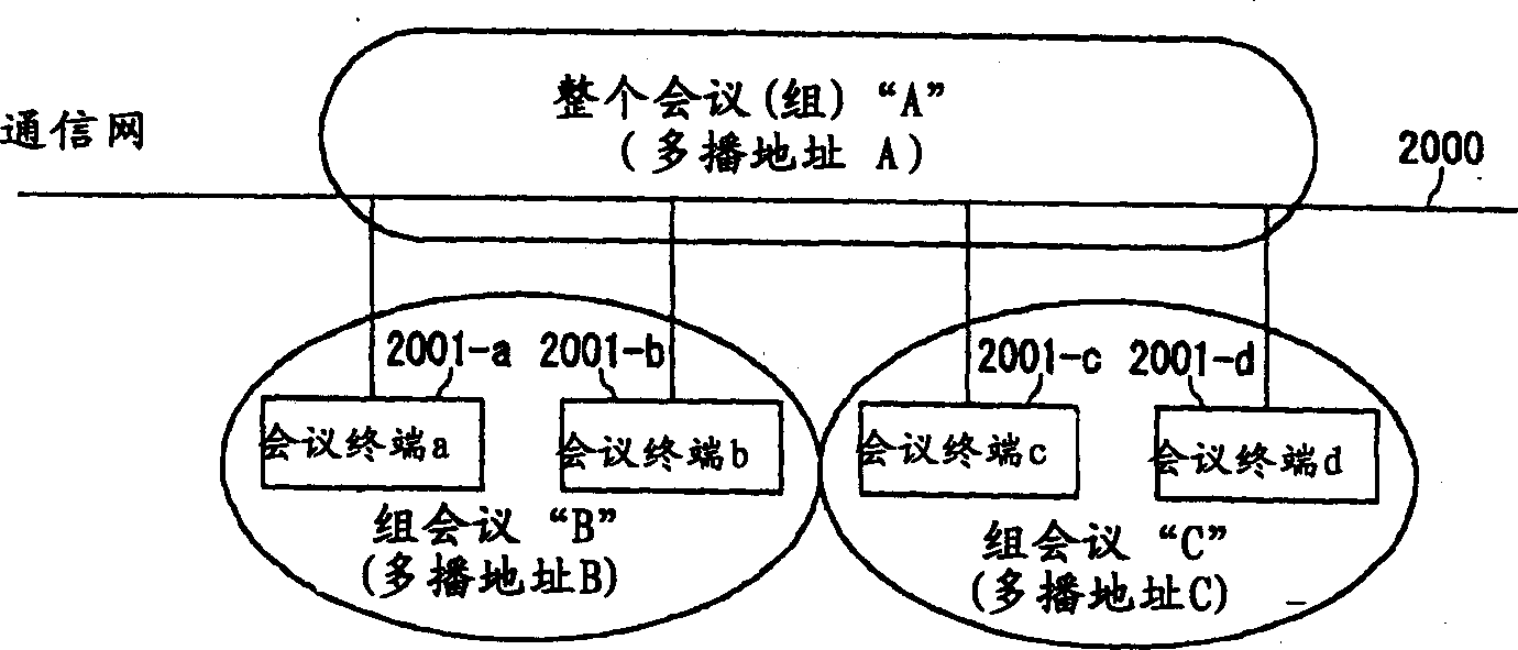
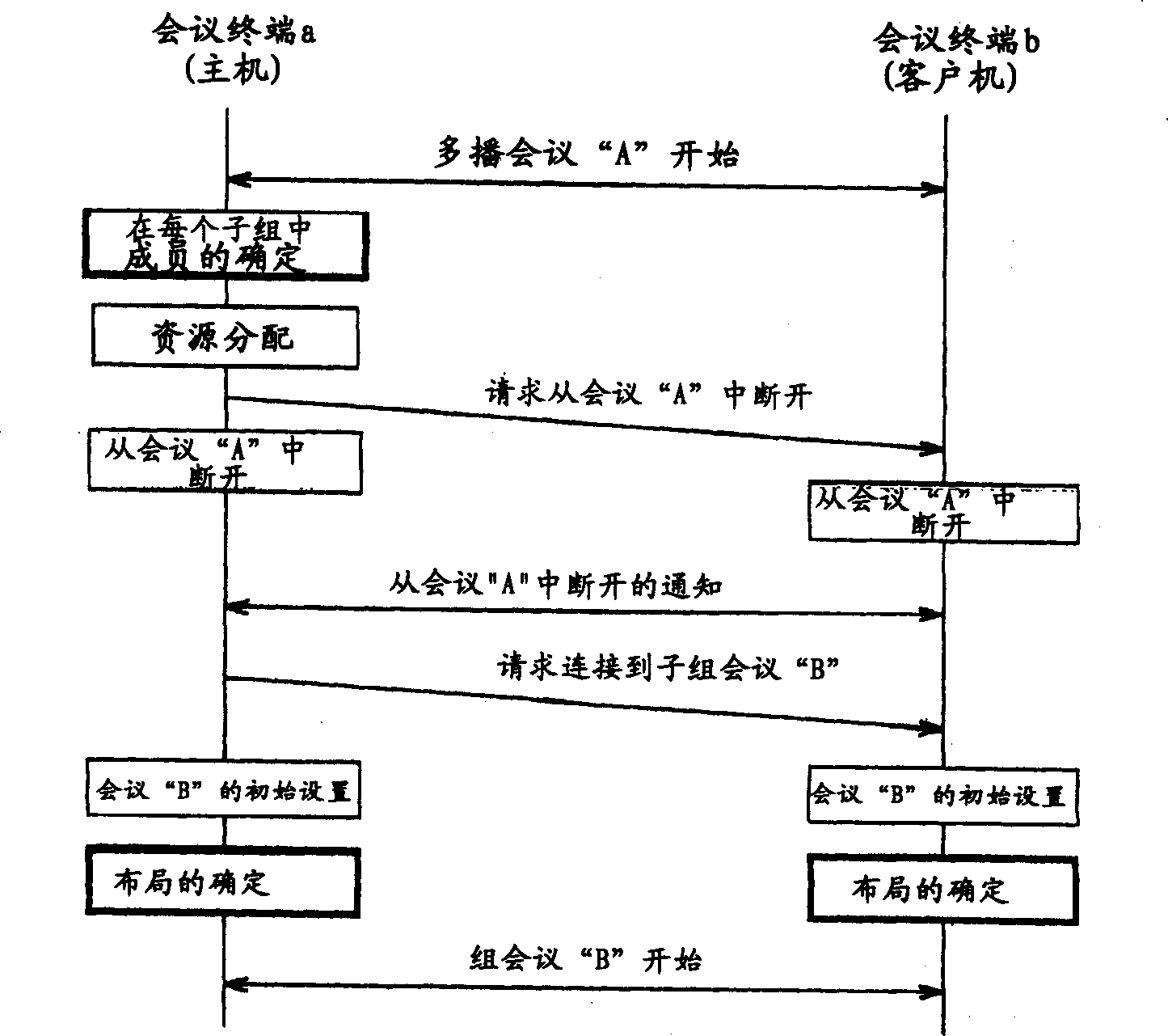
[0057] In this embodiment, one group address is used as sub-address information indicating that conference terminals belong to the same divided group. When it is required to divide participants into groups in which the group address is the same for all participants, a common group address which was already used by all participants before the group division continues to be used in each divided group. In each newly divided group, only participants belonging to each group can continue a multicast conference.
[0058] The difference with the traditional system is: in the case that the participants with the same group address are divided into multiple groups, there is no need to assign a new group address to the con...
no. 2 example
[0086] see Figure 5 , 12 and 13, the second embodiment of the present invention is now described. Incidentally, in the second embodiment, the same reference numerals are used for those components that are the same as or similar to those in the first embodiment, and thus their explanations are omitted or simplified in order to avoid duplication of description. Such an explanation method will be applied to the third and fourth embodiments which will be described later.
[0087] The second embodiment provides another structure of a conference terminal dedicated to a multicast conference.
[0088] Figure 5 The entire configuration of a multicast conference system according to the second embodiment is also illustrated. In this embodiment, the client conference terminal 100-2 will now be representatively detailed as follows.
[0089] Figure 12 detailed Figure 5 The structure of terminal 100-2 is shown. exist Figure 12 , now focus on explaining the operations of each co...
no. 3 example
[0103] see Figure 5 , 14 -17. Now, the third embodiment of the present invention will be described.
[0104] The third embodiment provides another terminal structure, which preferably can be used as the host (or chairman) conference terminal of a multicast conference. In this embodiment, it is necessary for such a terminal (hereinafter referred to as a host conference terminal) to have a function of issuing grouped requests to other client conference terminals.
[0105] Figure 5 The entire configuration of a multicast conference system according to the third embodiment is also illustrated. In this embodiment, the terminal 100-1 as a host conference terminal will now be described in detail as follows.
[0106] Figure 14 detailed Figure 5 The structure of terminal 100-1 is shown. exist Figure 14 , now focus on explaining the operations of each component, such as a newly introduced group member determination unit 301 , scene rewriter 204 and data reception control un...
PUM
 Abstract
Description
Claims
Application Information
 - R&D
- Intellectual Property
- Life Sciences
- Materials
- Tech Scout
- Unparalleled Data Quality
- Higher Quality Content
- 60% Fewer Hallucinations
Browse by: Latest US Patents, China's latest patents, Technical Efficacy Thesaurus, Application Domain, Technology Topic, Popular Technical Reports.
© 2025 PatSnap. All rights reserved.Legal|Privacy policy|Modern Slavery Act Transparency Statement|Sitemap|About US| Contact US: help@patsnap.com


