Syringe pump

A technology of syringe pump and syringe, which can be applied to syringes, auto-injectors, hypodermic instruments, etc., can solve problems such as patient harm

Inactive Publication Date: 2002-07-17
SMITHS GRP PLC
View PDF2 Cites 14 Cited by
  • Summary
  • Abstract
  • Description
  • Claims
  • Application Information

AI Technical Summary

Problems solved by technology

In some cases, this situation can bring harm to the patient

Method used


Image

  • Syringe pump
  • Syringe pump

Examples


Embodiment Construction

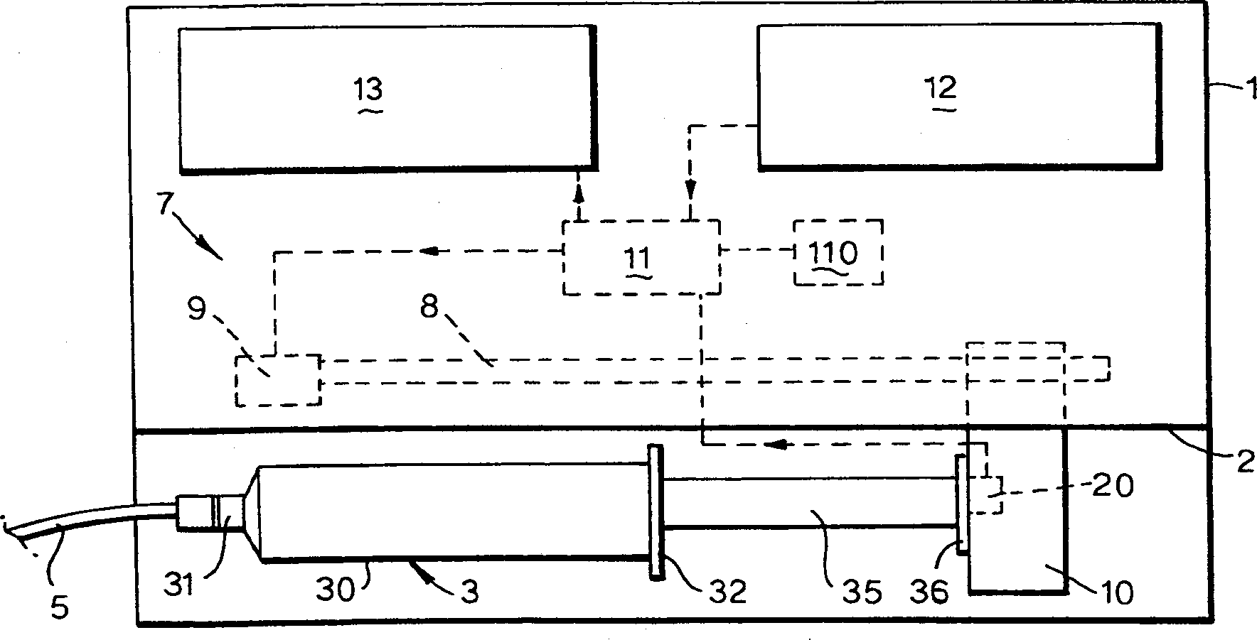
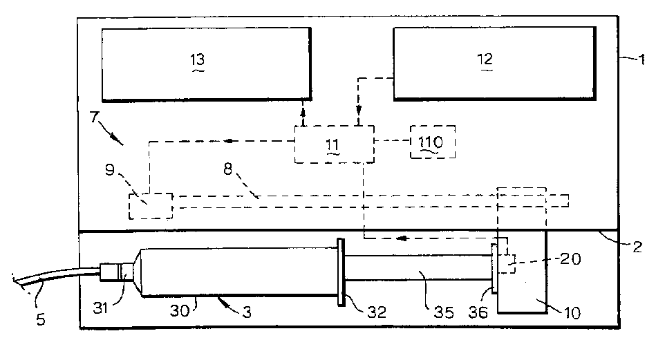
[0008] The pump has a housing 1 with a recess 2 on its front face, shaped to accommodate a normal syringe 3 . The syringe 3 has a cylindrical barrel 30 , a liquid outlet 31 at the front end of the cylindrical barrel, and a flange 32 at the rear end. The liquid outlet 31 is connected to the infusion tube 5, so by pushing the plunger 35, the medicinal solution in the syringe 3 can be injected into the patient through the infusion tube. The pump has a drive mechanism 7 comprising a lead screw 8 driven by an electric motor 9 . The limiting mechanism 10 can move with the rotation of the lead screw, and engage with the pressure head 36 of the plunger 35 , thereby pushing the plunger to move along the cylinder 30 . The motor 9 is driven by a control device 11 which receives input from a keyboard 12, or other user input means, as well as various sensors. The control device 11 can also output output information to a display 13 .

[0009] The plunger pressure head limiter 10 includes...


PUM


Abstract

A syringe pump has a motor rotating a leadscrew, which drives a plunger head retainer to push a plunger along the barrel of a syringe so as to dispense medication to a patient. A force sensor in the head retainer measures the force on the plunger to detect when there is an occlusion restricting flow of medication. When an excess force is detected an alarm is generated and the motor is reversed to reduce the force to about 10% of that at which the occlusion is detected. The occlusion can be removed with a reduced risk of a bolus of medication being dispensed after which the user restarts the pump so that the plunger is driven normally.

Description

field of invention [0001] The present invention relates to a syringe pump suitable for certain syringes. The syringe pump includes a plunger movable along the barrel, and the pump includes an occlusion detector responsive to an occlusion of the syringe flowing out of the drug fluid. Background technique [0002] Syringe pumps are used to deliver medical fluids from filled syringes to patients through infusion tubing. The syringe pump exerts a force on the syringe plunger, causing the liquid medicine to flow into the infusion line at a controlled rate. There will usually be means to detect an obstruction of the flowing liquid in the pump, for example caused by a bend in the pipe, and in response to said obstruction, stop the pump and issue an audible warning. The occurrence of clogging can be detected by measuring the force exerted by the pump drive on the plunger head, and excessive force can be detected. A strain sensor is mounted on the plunger head stop as described in...

Claims


Application Information

Patent Timeline
Patent Type & Authority Applications(China)
IPC IPC(8): A61M5/00A61M5/145A61M5/168
CPCA61M5/1456A61M5/16854A61M2205/18A61M2005/16863
Inventor R·J·特伯C·皮克斯
Owner SMITHS GRP PLC
Why Eureka
Try Eureka