Self-guiding punch and die set

A self-guiding, punching technology, applied in the direction of forming tools, manufacturing tools, metal processing, etc., can solve the quality problems of finished parts, damage to punches and die device tools, etc.

Inactive Publication Date: 2002-07-24
HUMDINGER
View PDF0 Cites 22 Cited by
  • Summary
  • Abstract
  • Description
  • Claims
  • Application Information

AI Technical Summary

Problems solved by technology

[0008] There are problems with punches and die assemblies: These problems can cause quality problems of finished parts and damage to punch and die assemblies tooling
There is a need in the art to reduce or eliminate angular alignment errors and improve positioning accuracy without adding much complexity to the structure of the die and press

Method used


Image

  • Self-guiding punch and die set
  • Self-guiding punch and die set
  • Self-guiding punch and die set

Examples


Embodiment Construction

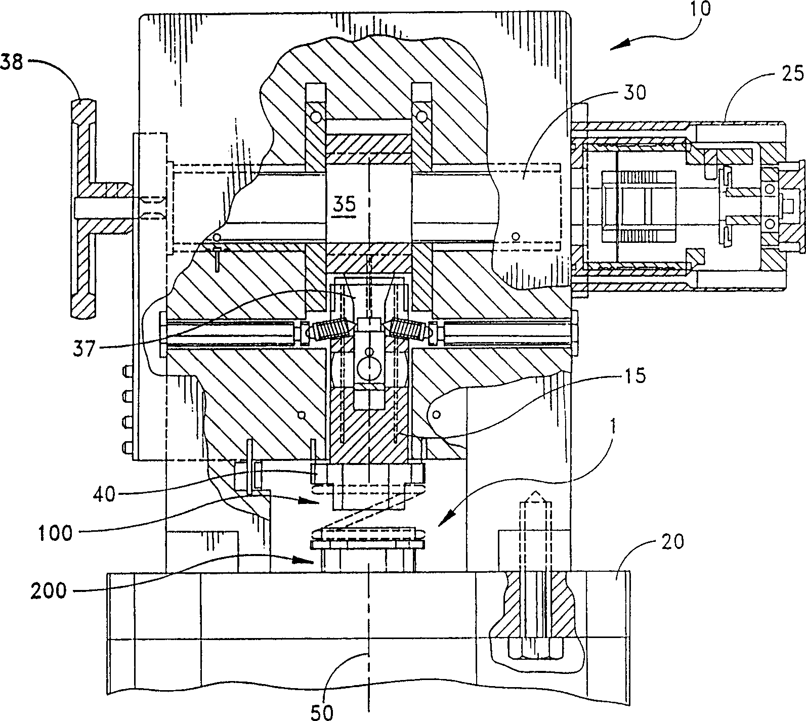
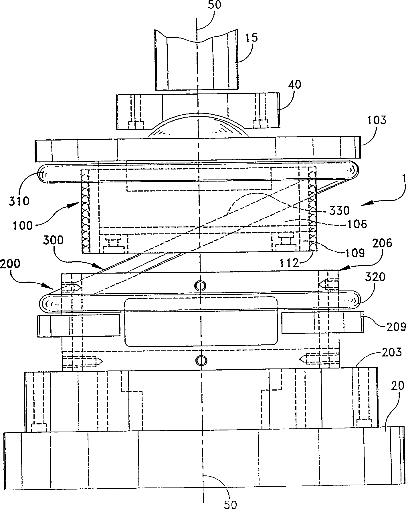
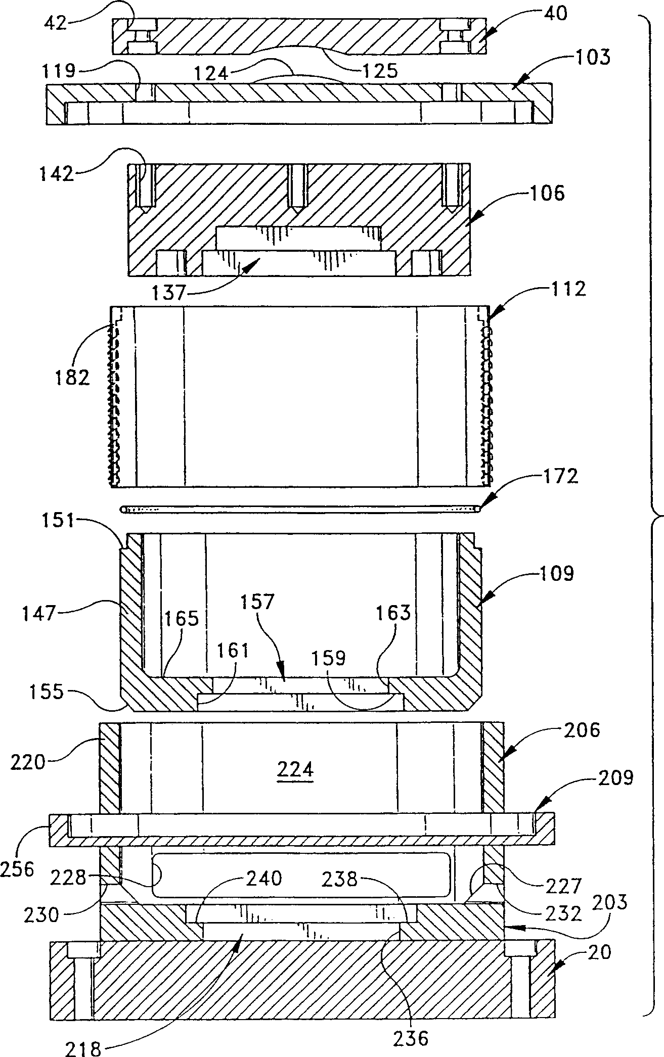
[0039] The following description of preferred embodiments of the invention is read in conjunction with the above accompanying drawings and should be considered a part of the overall description of the invention. As used in the specification, terms such as "horizontal", "vertical", "left", "right", "upper" and "lower" are used to denote orientations illustrated in particular drawings etc., and these do not The invention is limited to these particular orientations. Likewise, terms such as "inwardly" and "outwardly" generally refer to the proper orientation of a surface relative to its axis of tension or rotation. In addition, terms such as "coupled", "connected" or "interconnected" are used to describe a relationship between two or more structures, meaning that these structures are fixed or connected to each other directly or indirectly through intervening structures, and include Rotatable connection. The term "operably" means that the above direct or indirect connection betwe...


PUM


Abstract

A punch and die set is provided for use in a stamping press having a punch assembly and a die assembly reciprocated by a driving mechanism. The punch and die assemblies are aligned to a common center and are structured to slidably engage one another for positive guidance of the punch and die tools without the need for other guidance by shafts, bars or the like. One of the punch assembly and die assembly can be non-fixedly carried by the drive mechanism, allowing the guidance of the engaged punch and die assemblies to define the relative positions of the tools. This arrangement eliminates any stack-up of tolerances between the assemblies and substantially reduces misalignment during stamping, including any misalignment that may be introduced by the press driving mechanism.

Description

technical field [0001] This invention relates to metal forming and stamping machines in which opposing punch and die tools are joined over the length of a compressible workpiece, such as sheet metal. According to one aspect of the invention, cooperating tools such as punches and complementary dies are mounted on opposing tool-carrying structures which are free to complement each other, i.e. engage each other around the edges to guide in a male-female guiding arrangement , In stamping work, when the punch and die tool are combined on the workpiece, this guide arrangement accurately and repeatably determines the relative position of the punch and die tool. Background technique [0002] In the traditional technique used to manufacture certain objects, especially some objects from flat metal strips, the conditioned material is fed into a specially manufactured tool called a punching machine, which is equipped with a stamping die . The stamping die and other related structures ...

Claims


Application Information

Patent Timeline
Patent Type & Authority Applications(China)
IPC IPC(8): B21D28/14B21D28/34B21D37/10B21D37/12
CPCB21D28/14B21D37/12Y10T83/828Y10T83/8702Y10T83/8704Y10T83/874Y10T83/8785Y10T83/8821Y10T83/8878B26D5/00
Inventor 迈克尔·施罗特托马斯·鲁尼
Owner HUMDINGER
Why Eureka
Try Eureka