Liquid crystal display device and method for decreasing scintillation

A technology for liquid crystal displays and liquid crystal panels, which is applied to static indicators, instruments, components of color TVs, etc., and can solve the problems of increasing the amount of flicker, aggravating the flicker, and deviation from the optimal state.

Inactive Publication Date: 2002-07-31
SAMSUNG DISPLAY CO LTD
View PDF3 Cites 17 Cited by
  • Summary
  • Abstract
  • Description
  • Claims
  • Application Information

AI Technical Summary

Problems solved by technology

Therefore, the common electrode voltage may deviate from the optimal state, thus aggravating the flickering
In particular, large liquid crystal displays with high resolution may exponentially increase the amount of flicker perceptible to the naked eye

Method used


Image

  • Liquid crystal display device and method for decreasing scintillation
  • Liquid crystal display device and method for decreasing scintillation
  • Liquid crystal display device and method for decreasing scintillation

Examples


Embodiment Construction

[0015] The present invention will now be described more fully with reference to the accompanying drawings, in which preferred embodiments of the invention are shown. However, the present invention can be embodied in many different forms and is not limited to the embodiments set forth herein. All like reference numbers refer to like elements.

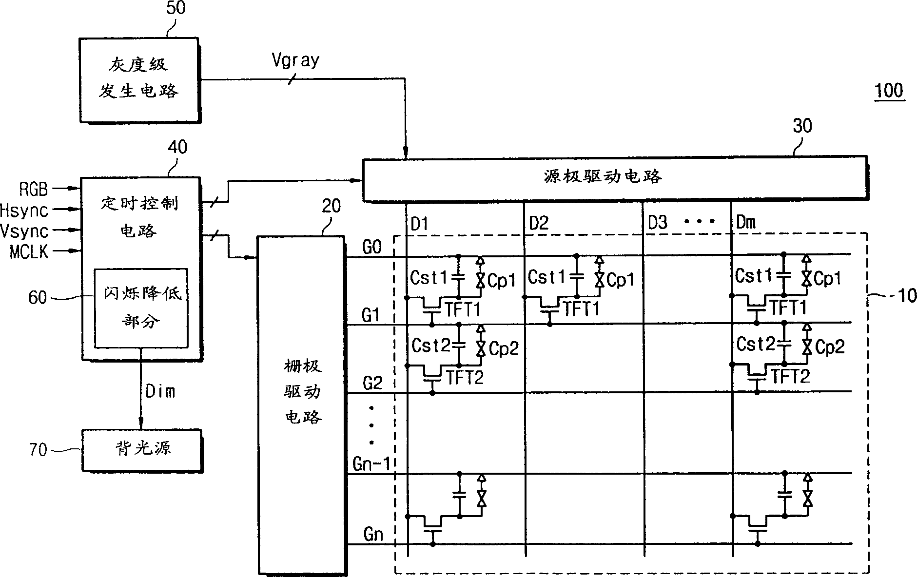
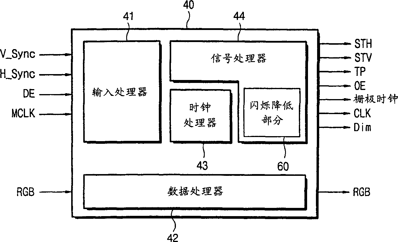
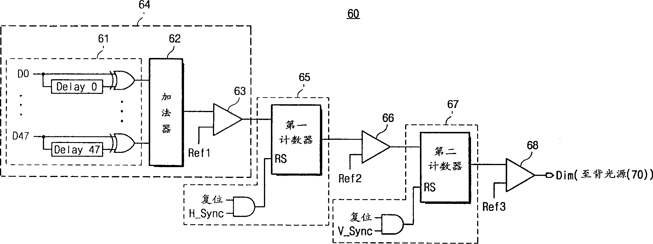
[0016] A liquid crystal display according to the present invention includes: a timing control circuit having a flicker reducing section for detecting the amount of flicker included in a complete frame to be displayed on the liquid crystal panel, and controlling the brightness of the backlight according to the detected amount of flicker . When the detected flicker is greater than the allowable value, the timing control circuit generates a control signal to dim (dim) the brightness of the backlight, which can obviously reduce the amount of flicker recognizable by naked eyes.

[0017] figure 1 is a schematic block diagram of an LCD 100 a...


PUM


Abstract

An LCD device includes a timing control circuit having a flicker reducing portion for detecting flickers in the entire one frame to be displayed in a liquid crystal panel and controlling a brightness of the backlight according to an amount of detected flickers. The timing control circuit can evidently reduce visually recognized flickers by dimming the brightness of the backlight when the detected flickers is more than given rate.

Description

technical field [0001] The present invention relates to a liquid crystal display (LCD), and more particularly, to an active matrix type LCD using a thin film transistor (TFT) as a switching element and a method for reducing flicker. Background technique [0002] In an active matrix LCD, all pixels are driven by a plurality of active elements having nonlinear characteristics, and each active element is arranged on each pixel arranged in an array shape. TFT elements are usually used as active elements. [0003] In a liquid crystal display, light display characteristics depend on TFT elements, liquid crystal materials, cell gaps, color filters, and the like. Therefore, when the TFT LCD is used for a long period of time, flickering or image sticking may occur in which display characteristics deteriorate. [0004] In order to reduce flicker, various methods have been proposed. In U.S. Patent No. 5,253,091, issued to Kimura et al., October 1993, entitled...

Claims


Application Information

Patent Timeline
Patent Type & Authority Applications(China)
IPC IPC(8): G02F1/133G09G3/20G09G3/34G09G3/36H04N5/66
CPCG09G2320/0247G09G3/3648G09G2320/0626G09G3/3406G02F1/133
Inventor 朴倖源田万福罗根植
Owner SAMSUNG DISPLAY CO LTD
Why Eureka
Try Eureka